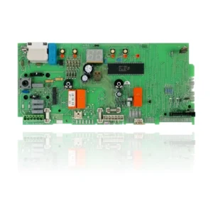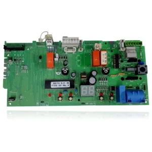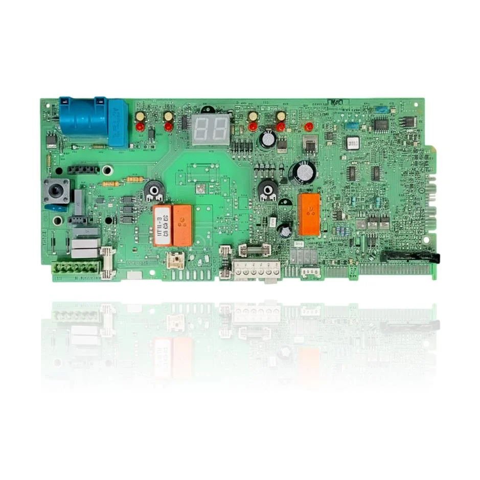
Junkers Euromaxx ZWC28 1MF2A PCB Ref. 87172076530
The Junkers Euromaxx ZWC28 1MF2A PCB, with reference 87172076530, is the component that controls the ignition, burner modulation, pump, and safety features of the boiler. If it malfunctions, the boiler may fail to start, become locked, or operate erratically, potentially displaying the fault code F0. This PCB is compatible with the Junkers Euromaxx ZWC28-1MF2A model, among others. Replacement is recommended when these symptoms of malfunction are detected.
VAT included
Consult via WhatsAppBosch Junkers boilers compatible with reference 87172076530 2
PCB with reference 87172076530 2. A proven compatibility: Euromaxx ZWC28-1MF2A.
Proven compatibility
| Boiler model | Family | Verification |
|---|---|---|
| Bosch Junkers Euromaxx ZWC28-1MF2A | Junkers | Contrasted |
Can't see your model or have questions? The printed reference takes precedence. How to check it · Send us a photo via WhatsApp.
How to check if the ref. 87172076530 2 is the part for your boiler.
What determines it is not the boiler model, but the reference printed on the part you already have installed.
- Find the reference printed on the installed part and check whether it matches the catalogue reference 87172076530 2. If it is not visible, do not identify the part from its shape alone.
- Check the full boiler model on its data plate and look for it in the model associations on this page.
- Compare the connections and physical body with the original part before installation.
- If anything is unclear, send us a photo of the marking via WhatsApp before placing your order.
Symptoms and faults that the PCB 87172076530 2 resolves
The PCB controls the ignition, modulation, and safety features of the boiler. These are the typical symptoms and what to do:
Common symptoms and faults
- 01
The boiler does not turn on: there are no lights, no display, and no indicators respond.
Cause: The PCB is the one that powers and controls the entire system; if it fails to start, the boiler will not operate even if power is supplied.
Check that the fuse on the PCB is not blown and that the boiler is receiving mains voltage before replacing it.
- 02
The boiler locks out with a fault code and, upon resetting, it locks out again immediately with the same code.
Cause: The PCB interprets the signals from the safety sensors; a fault in it can cause repeated lockouts even if those components are functioning properly.
Note the exact code and first check the component indicated (sensor, pressure switch, flame detector) before declaring the PCB faulty.
- 03
It requests ignition, you can hear the spark attempt but the flame does not ignite.
Cause: The PCB controls the ignition sequence and the generation of the spark; if it fails in its ignition, the command does not reach the electrode.
Check that there is gas and network pressure before assuming that the fault is with the PCB.
- 04
The room thermostat is calling for heat, but the boiler is not responding, as if it doesn't hear it.
Cause: The PCB receives the demand from the thermostat through its connection terminals; if that input fails, the boiler ignores the request.
Check the wiring and terminals of the thermostat in the boiler before replacing the PCB.
Fault codes for Bosch Junkers that this part resolves.
| Code | Fault | Diagnosis and solution |
|---|---|---|
| F0 | Internal fault\PCB fault | Internal fault of the PCB (Heatronic/PCB) detected by self-diagnosis; it is verified by checking connections and power supply of the printed circuit, and if it persists, replacing the PCB. |
These symptoms can have more than one cause. If your boiler displays a fault code, send it to us via WhatsApp along with a photo of the labeling, and we'll tell you if this is the part.
Data sheet for the Bosch Junkers PCB 87172076530 2
- Catalogue reference
- 87172076530 2
- Brand
- Bosch Junkers
- Type of part
- PCBs (control boards)
- Units in stock
- 2 units
- Status
- Refurbished
- Warranty
- 1 year
- Shipping
- Delivery time shown at checkout
- Return
- 14 days
Data read on the part and in the manufacturer's documentation
What we have not been able to verify does not appear here.
- Relay marking on the PCB
- HT 11-3 / CR GA 6C
Frequently asked questions about the PCB 87172076530 2
What does the marking "HT 11-3 / CR GA 6C" on the plate mean?
Does this PCB work for other Junkers Euromaxx boilers besides the ZWC28-1MF2A?
Spare parts related to Bosch Junkers Junkers