






























































Short answer
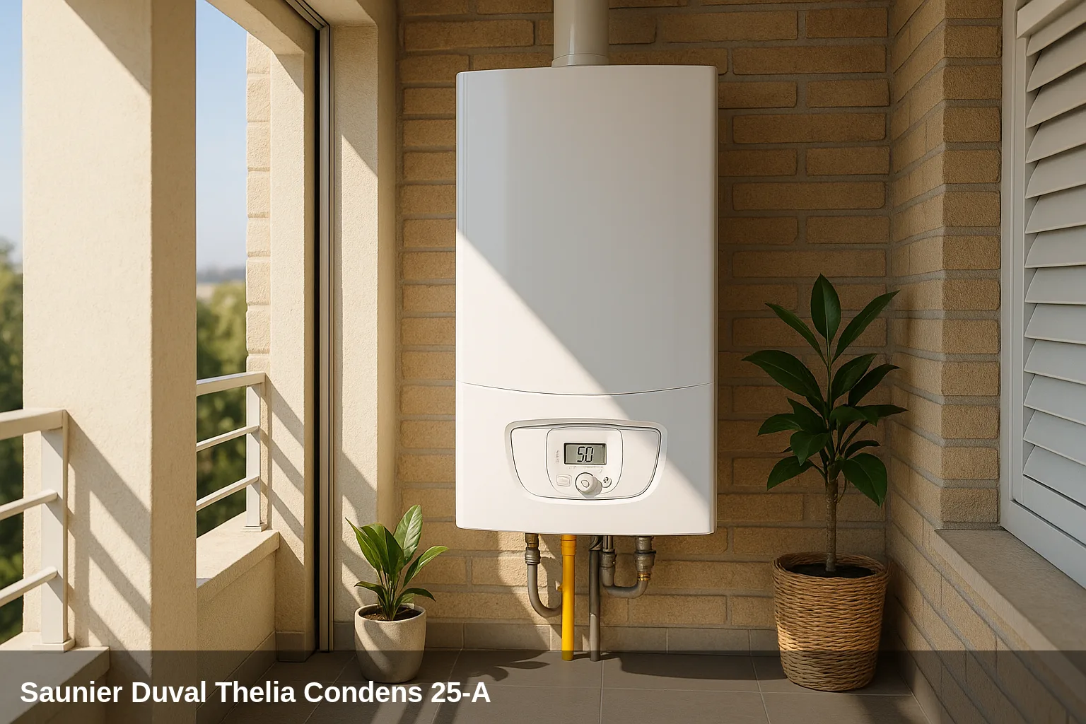
The Saunier Duval Thelia Condens 25-A It is a wall-mounted gas condensing combination boiler of 25 kW, part of the technical platform of the Vaillant group, with an aluminium-silicon heat exchanger, Warm Start function, and high-contrast display with self-diagnosis. It shares electronic architecture and fault codes F.xx with the Semia Condens models and other variants of the same range. It is available in versions with different chronothermostats (Exacontrol, MiGo) and in heating-only configuration (Thelia Condens N).
Error code table for the Thelia Condens 25-A
Quick summary of all fault codes. Below you have the details of each one with its cause and solution.
| Code | Meaning |
|---|---|
| F.00 | Flow temperature sensor interruption |
| F.01 | Return temperature sensor interruption |
| F.10 | Short circuit in the flow temperature sensor |
| F.11 | Short circuit in the return temperature sensor |
| F.20 | Safety shutdown: overheating temperature reached |
| F.22 | Safety shutdown: lack of water in the boiler |
| F.23 | Safety shutdown: excessive temperature variation |
| F.24 | Safety shutdown: temperature rise too fast |
| F.27 | Incorrect flame detection (flame without ignition request) |
| F.28 | Ignition fault on start-up: the boiler fails to ignite after several attempts |
| F.29 | Flame loss during operation |
| F.32 | Fan frost protection active: fan speed out of range |
| F.33 | Fan frost protection active: air controller fault (pressure switch) |
| F.49 | eBUS error: intensity too low |
| F.61 | Gas valve control fault |
| F.62 | Fault in the gas valve disconnection controller |
| F.63 | EEPROM fault in the PCB |
| F.64 | Error in the electronics, sensor, or analog-to-digital converter |
| F.65 | Electronics temperature too high |
| F.68 | Unstable flame signal |
| F.70 | Invalid product code (DSN) |
| F.72 | Deviation between flow temperature sensor and water pressure sensor, or excessive difference between sensors |
| F.73 | Water pressure sensor signal too low (interruption or short circuit to ground) |
| F.74 | Water pressure sensor signal too high (short circuit to voltage) |
| F.77 | Condensate or flue system error (non-return flap) |
| F.83 | Burner sensor error: no temperature change registered at start-up |
| F.84 | Implausible difference between flow and return temperature sensors |
| F.85 | Installation error of the flow and/or return temperature sensors |
| F.87 | Electrode fault (ignition/ionisation) |
| F.88 | Gas valve wiring fault |
| F.89 | Wiring error in the circulation pump |
What can you check yourself?
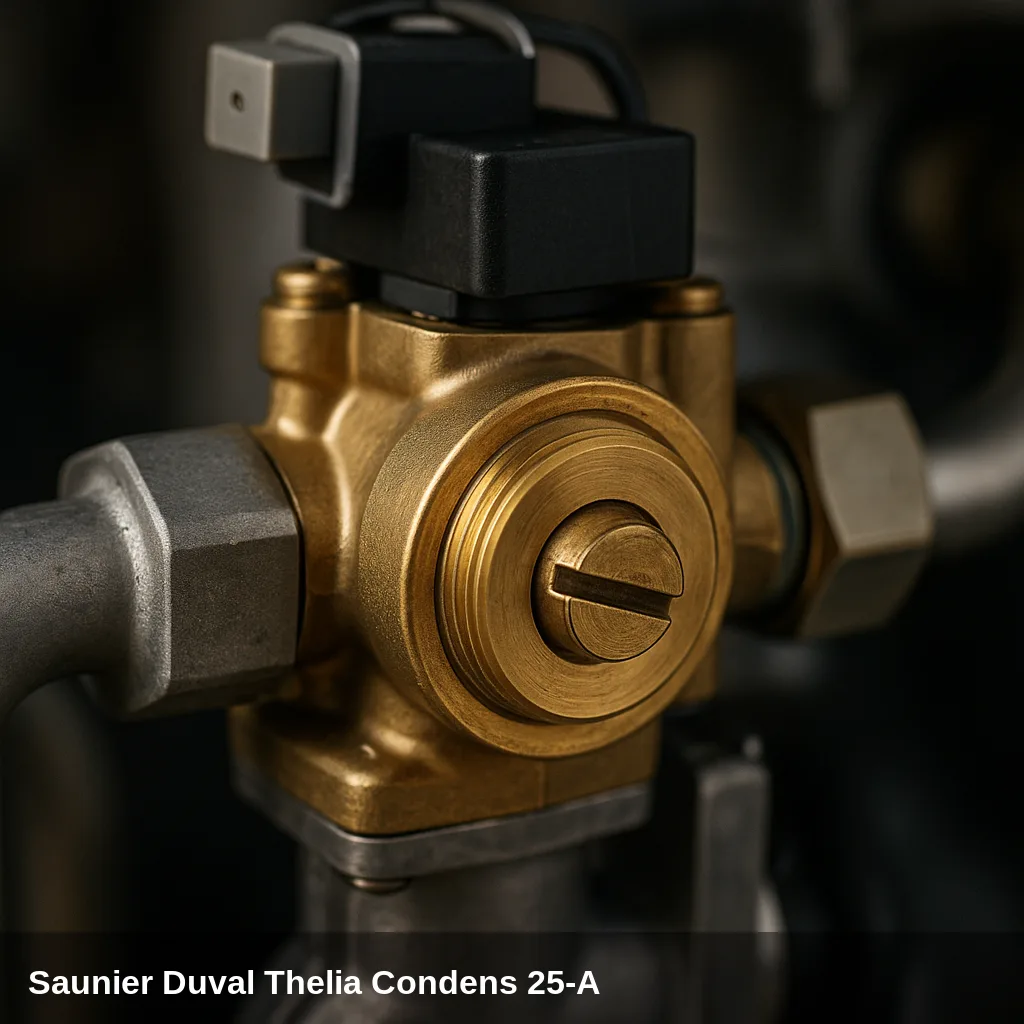
Some alerts can be resolved with simple and safe checks: replenishing the water pressure, bleeding the air from the radiators, checking that the gas valve is open, or resetting the boiler after a temporary lockout. If the code reappears after doing this, there is an underlying cause that should be reviewed by a qualified technician. Do not manipulate internal gas components nor electronics.
How to replenish the pressure step by step
- Locate the filling valve under the boiler.
- Open it slowly while observing the pressure gauge.
- Close the valve upon arrival at between 1 and 1.5 bar in cold.
- Bleed the radiators starting with the furthest one and check the pressure again.
- Reset the boiler; if the pressure warning disappears, the problem was resolved.
All fault codes and their solution
F.00 — Flow temperature sensor interruption
Why does it appear: NTC connector disconnected or loose, interruption in the wiring harness, defective flow NTC sensor, or poorly seated PCB multi-connector.
What to do: Check the connection of the NTC sensor connector for the flow and the multi-connector on the PCB. If the wiring and connections are correct, the NTC sensor should be inspected or replaced by a qualified technician.
Affected component: Temperature sensor
F.01 — Return temperature sensor interruption
Why does it appear: Return NTC connector disconnected or loose, interruption in wiring, defective return NTC sensor.
What to do: Check the connection of the return NTC connector and the integrity of the cable. If the connectors are correct, the return sensor should be inspected or replaced by a qualified technician.
Affected component: Temperature sensor
F.10 — Short circuit in the flow temperature sensor
Why does it appear: NTC sensor for flow internally faulty or short circuit in the wiring harness to the control board.
What to do: Check the wiring for a short circuit. If the wiring is correct, the flow NTC sensor should be replaced by a qualified technician.
Affected component: Temperature sensor
F.11 — Short circuit in the return temperature sensor
Why does it appear: Return NTC sensor faulty or short circuit in the cable to the control board.
What to do: Check the wiring for a short circuit. If it is correct, the return NTC sensor must be replaced by a qualified technician.
Affected component: Temperature sensor
F.20 — Safety shutdown: overheating temperature reached
Why does it appear: Blocked or defective circulation pump, air in the hydraulic circuit, loose contact on the inlet or return NTC sensors, faulty pump capacitor, stuck priority valve, or incorrect grounding of the wiring harness.
What to do: Reset the boiler by pressing the reset button. If the fault repeats, a qualified technician should check the circulation pump, bleed the air from the circuit, and inspect the connections of the NTC sensors and the wiring.
Affected component: Circulation pump
F.22 — Safety shutdown: lack of water in the boiler
Why does it appear: Heating circuit pressure below minimum (generally below 0.5 bar), defective water pressure sensor, cable to the pump or pressure sensor loose, disconnected or faulty, or water loss in the installation.
What to do: Replenish the pressure of the heating circuit to the indicated value (usually between 1 and 1.5 bar when cold) using the filling valve. If the fault persists after replenishing pressure, or if the pressure drops repeatedly, a qualified technician should locate the leak and check the pressure sensor.
Browse catalogue: Catalogue: spare parts · Saunier Duval
F.23 — Safety shutdown: excessive temperature variation
Why does it appear: Blocked circulation pump or insufficient flow, presence of air in the circuit, supply and return sensors reversed in their position.
What to do: A qualified technician should check the condition and operation of the circulation pump, bleed the circuit to remove air, and verify that the flow and return sensors are correctly positioned.
Affected component: Circulation pump
F.24 — Safety shutdown: temperature increase too rapid
Why does it appear: Blocked circulation pump, presence of air in the system, insufficient water pressure, or blocked anti-gravity brake.
What to do: A qualified technician should inspect the circulation pump, bleed the air from the hydraulic circuit, and check the system pressure.
Affected component: Circulation pump
F.27 — Incorrect flame detection (flame without ignition request)
Why does it appear: Humidity or condensation in the electronics, defective flame control electronics, leak in the gas solenoid valve allowing gas passage when it shouldn't.
What to do: This fault indicates a potential safety issue with the gas valve. A qualified technician should inspect the gas valve, the flame control electronics, and check the gas circuit for leaks.
Browse catalogue: Catalogue: gas valves · Saunier Duval
F.28 — Ignition fault on start-up: the boiler fails to ignite after several attempts
Why does it appear: Gas supply interrupted or insufficient (gas valve closed, low pressure), ignition/ionisation electrode dirty, mispositioned or faulty, defective gas valve, blocked condensate line, obstructed flue, incorrect grounding or defective control board.
What to do: Check that the gas valve is open and that there is a gas supply to the building. If the supply is correct and the error persists, a qualified technician should clean or replace the ionisation electrode, verify the gas valve, and inspect the condensate and flue gas evacuation.
Affected component: Ignition/Ionisation Electrode
F.29 — Flame loss during operation
Why does it appear: Temporary interruption of gas supply, recirculation of combustion gases towards the air intake, dirty or misaligned ionisation electrode, obstruction in the flue outlet, or poor grounding.
What to do: Verify that the gas supply is continuous and that the flue is not obstructed. If the problem persists, a qualified technician should clean the ionisation electrode, check the combustion, and inspect the evacuation system.
Affected component: Ignition/Ionisation Electrode
F.32 — Fan frost protection active: fan speed out of range
Why does it appear: Fan connector disconnected or loose, obstruction in the air intake or flue outlet, fan blocked, defective fan Hall sensor, or fault in the PCB.
What to do: A qualified technician should inspect the fan connections, check that the air and flue conduits are not obstructed, and verify the operation of the fan and its speed sensor.
Browse catalogue: Catalogue: flue fans · Saunier Duval
F.33 — Anti-freeze protection of the fan active: air controller fault (pressure switch)
Why does it appear: The differential pressure switch does not activate correctly, pressure switch connector disconnected or loose, air inlet or pressure switch orifice blocked, pressure tube blocked.
What to do: A qualified technician should inspect the differential pressure switch, its connections, and the pressure tubes, as well as check that the air intake and flue gas exhaust conduits are not obstructed.
Browse catalogue: Catalogue: flue fans · Saunier Duval
F.49 — eBUS error: intensity too low
Why does it appear: Short circuit in the eBUS, overload on the bus, reversed polarity in the bus power connection, or faulty external device connected.
What to do: A qualified technician should verify the eBUS wiring, check the polarity of the connection, and inspect the external devices connected to the bus (thermostats, chronothermostats).
Affected component: Electrical installation
F.61 — Gas valve control fault
Why does it appear: Short circuit in the cable to the gas valve, defective gas valve, or fault in the control board electronics.
What to do: A qualified technician should inspect the wiring and connections of the gas valve. If the wiring is correct, the gas valve or the control board should be evaluated.
Browse catalogue: Catalogue: gas valves · Saunier Duval
F.62 — Fault in the gas valve shut-off controller
Why does it appear: The gas valve takes too long to disconnect, incorrect flame signal or non-hermetic gas valve (internal leak).
What to do: A qualified technician should verify the correct closure of the gas valve and the integrity of the control electronics. If the valve does not close properly, it must be replaced.
Browse catalogue: Catalogue: gas valves · Saunier Duval
F.63 — EEPROM error on the PCB
Why does it appear: Fault in the memory of the PCB, usually due to an internal fault of the control board itself.
What to do: A qualified technician should diagnose and, if necessary, replace the PCB (control board).
Browse catalogue: Catalogue: circuit boards · Saunier Duval
F.64 — Error in the electronics, sensor, or analogue-digital converter
Why does it appear: Short circuit in the NTC sensor for flow or return that saturates the A/D converter of the PCB, or internal fault in the control electronics.
What to do: A qualified technician should check the NTC sensors for a short circuit and, if they are correct, evaluate the PCB.
Browse catalogue: Catalogue: circuit boards · Saunier Duval
F.65 — Temperature of the electronics too high
Why does it appear: Excessive external heat source in the boiler environment or internal fault in the PCB.
What to do: Verify that there is no external heat source affecting the boiler. If the ambient temperature is correct, a qualified technician should evaluate the PCB.
Browse catalogue: Catalogue: circuit boards · Saunier Duval
F.68 — Unstable flame signal
Why does it appear: Air in the gas (especially during initial start-up or after an interruption), insufficient gas pressure, incorrect excess air factor (combustion adjustment), or interruption in the ionization circuit.
What to do: Check the gas supply and bleed the air from the pipes if the boiler is new or has been unused. If the problem persists, a qualified technician should adjust the combustion and check the ionisation electrode.
Affected component: Ignition/Ionisation Electrode
F.70 — Invalid product code (DSN)
Why does it appear: The control display and the PCB have been replaced simultaneously without readjusting the appliance identification code, or the power coding resistor is incorrect.
What to do: A qualified technician must reconfigure the product code (DSN) in the boiler after the component change. It is not a usual operational fault.
Browse catalogue: Catalogue: circuit boards · Saunier Duval
F.72 — Deviation between flow temperature sensor and water pressure sensor, or excessive difference between sensors
Why does it appear: Temperature difference between flow sensor and return sensor less than -6 K, sensors defective or incorrectly positioned.
What to do: A qualified technician should check the positioning and condition of the flow and return temperature sensors, and verify the correct circulation of the water.
Affected component: Temperature sensor
F.73 — Water pressure sensor signal too low (interruption or short circuit to ground)
Why does it appear: Interruption in the pressure sensor cable, short circuit to ground, or defective pressure sensor.
What to do: A qualified technician should inspect the wiring of the pressure sensor and replace the sensor if it is faulty.
Browse catalogue: Catalogue: spare parts · Saunier Duval
F.74 — Water pressure sensor signal too high (short circuit to voltage)
Why does it appear: Short circuit in the pressure sensor cable to the 5V or 24V supply, or internal fault in the pressure sensor.
What to do: A qualified technician should inspect the wiring of the pressure sensor for a short circuit and replace the sensor if necessary.
Browse catalogue: Catalogue: spare parts · Saunier Duval
F.77 — Fault in the condensate or flue system (non-return flap)
Why does it appear: The non-return flap for combustion gases is not responding or is faulty, or the condensate pump (if the installation has one) is presenting a fault.
What to do: A qualified technician should inspect and clean or replace the flue gas non-return flap and check the condensate drainage system.
Affected component: Heat exchanger
F.83 — Burner sensor error: no temperature change registered at start-up
Why does it appear: When the burner starts, there is no sufficient temperature variation detected in the flow or return sensors, indicating insufficient water in the circuit or a temperature sensor improperly positioned in the pipe.
What to do: A qualified technician must verify that the circuit has sufficient water and that the temperature sensors are correctly positioned and in contact with the pipe.
Affected component: Temperature sensor
F.84 — Implausible difference between flow and return temperature sensors
Why does it appear: The flow and return temperature sensors are swapped with each other (reversed) or incorrectly mounted, generating a negative difference greater than -6 K.
What to do: A qualified technician must verify that the flow and return sensors are installed on the correct pipe and with the correct orientation.
Affected component: Temperature sensor
F.85 — Installation error of the flow and/or return temperature sensors
Why does it appear: The flow and return temperature sensors have been installed on the same pipe, on the incorrect pipe, or are not properly connected.
What to do: A qualified technician should check the physical installation of the temperature sensors and correct their location if it is incorrect.
Affected component: Temperature sensor
F.87 — Fault in the electrodes (ignition/ionisation)
Why does it appear: Ignition or ionization electrode disconnected, electrode cable short-circuited, or electrode in poor condition.
What to do: A qualified technician should check the connections of the electrodes, the condition of the cable, and the electrode itself, replacing it if it is deteriorated.
Affected component: Ignition/Ionisation Electrode
F.88 — Gas valve wiring error
Why does it appear: Gas valve disconnected from the boiler wiring or short circuit in the cable to the valve.
What to do: A qualified technician should inspect and correctly reconnect the wiring of the gas valve and rule out any short circuits.
Browse catalogue: Catalogue: gas valves · Saunier Duval
F.89 — Circulation pump wiring error
Why does it appear: Circulation pump disconnected from the boiler wiring or short circuit in the cable to the pump.
What to do: A qualified technician should inspect and correctly reconnect the wiring of the circulation pump and rule out short circuits.
Affected component: Circulation pump
When to call a technician
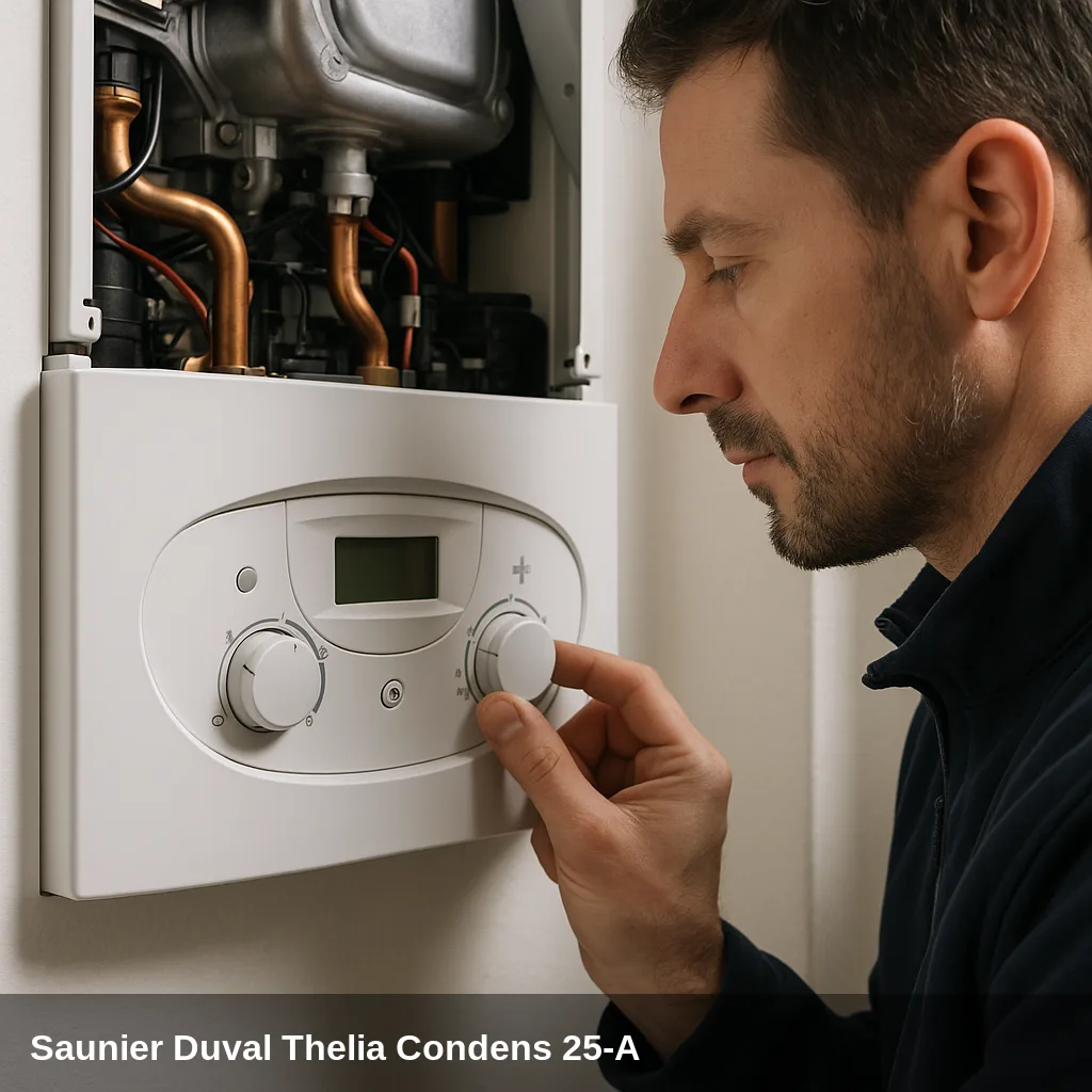
Fault codes related to sensors, electronics, gas valve, fan, or flue gas evacuation require a qualified technician with the appropriate equipment. If the same fault code reappears after a reset, or if the pressure drops repeatedly, a professional inspection is advisable. In Uniclima do you find spare parts for this boiler.
Frequently Asked Questions
Yes. The user can open the boiler's filling valve until the pressure gauge reads between 1 and 1.5 bar when cold, and then close it. If the pressure repeatedly drops again, there is a water leak in the system that should be diagnosed by a qualified technician.
F.28 indicates that the boiler has failed to ignite on startup after several attempts. F.29 indicates that the flame has gone out during normal operation. Both can have similar causes (gas supply, ionisation electrode), but F.29 points more towards occasional gas interruptions or flue gas evacuation problems that occur while running.
F.70 indicates that the product code (DSN) stored in the PCB is not consistent with the current equipment. It usually appears when both the control display and the PCB are replaced simultaneously without reconfiguring the appliance identification code. It can only be corrected using the diagnostic tool of qualified technical service.
If the manual reset does not resolve the error, or if the error reappears repeatedly, the boiler should not be attempted to be repaired without specific training. A qualified heating installer or technical service should be contacted, as they have the necessary diagnostic equipment to safely identify the root cause.