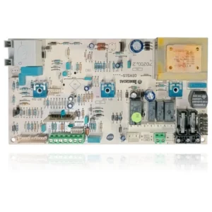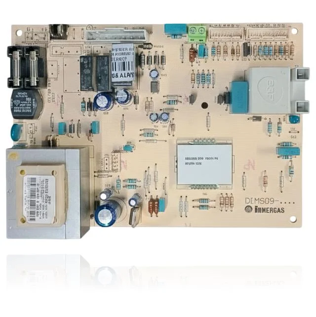
Immergas Eolo Star 23 kW PCB Bertelli Partners 1 Ref. 023947
The Immergas Eolo Star 23 KW Bertelli Partners 1 PCB, with reference 023947, is a component that controls the ignition, burner modulation, pump, and safety features of the boiler. If it has faults, you will notice that the boiler does not start, gets locked, or exhibits erratic behavior. This PCB is compatible with models such as Eolo Star 23 KW, Eolo Star 24 KW, Eolo Star 24 3 E, and Nike Star 23 KW, among others. It is advisable to replace it upon detecting these symptoms to avoid further issues.
VAT included
Consult via WhatsAppImmergas boilers compatible with reference 023947
PCB with reference 023947. Four confirmed compatibilities: Eolo Star 23 kW and Eolo Star 24 kW.
Proven compatibility
| Boiler model | Family | Verification |
|---|---|---|
| Immergas Eolo Star 23 kW | Eolo Star | Contrasted |
| Immergas Eolo Star 24 kW | Eolo Star | Contrasted |
| Immergas Eolo Star 24 3 E | Eolo Star | Contrasted |
| Immergas Nike Star 23 kW | Nike Star | Contrasted |
Can't see your model or have questions? The printed reference takes precedence. How to check it · Send us a photo via WhatsApp.
How to check if the reference 023947 is the part for your boiler
What determines it is not the boiler model, but the reference printed on the part you already have installed.
- Find the reference printed on the installed part and check whether it matches the catalogue reference 023947. If it is not visible, do not identify the part from its shape alone.
- Check the full boiler model on its data plate and look for it in the model associations on this page.
- Compare the connections and physical body with the original part before installation.
- If anything is unclear, send us a photo of the marking via WhatsApp before placing your order.
Symptoms and faults that the PCB 023947 resolves.
The PCB controls the ignition, modulation, and safety features of the boiler. These are the typical symptoms and what to do:
Common symptoms and faults
- 01
The boiler does not start at all, with no lights or indications on the panel.
Cause: If the PCB does not work, there is no electrical management, even if the main supply is correct.
Check the fuse on the PCB and verify that there is power reaching the connection terminal before replacing it.
- 02
Anomaly codes appear that change without a clear relationship between them.
Cause: A damaged PCB can give erroneous readings from its sensors and trigger different protections each time.
Note the codes that appear during several cycles: if they do not follow a fixed pattern, the problem is usually with the PCB.
- 03
The boiler control does not respond to any button, as if it were locked.
Cause: The microprocessor on the PCB manages the interface; if it fails, the buttons do not work.
Cut the power for a couple of minutes and check if the remote responds when you turn it back on.
- 04
The boiler ignites, runs for a moment, and then shuts off by itself without displaying any visible error.
Cause: An intermittent fault on the PCB can stop the cycle without registering a fault code.
Observe if the shutdown always occurs at the same point in the cycle, which helps to differentiate a PCB fault from another component.
Fault codes from Immergas that this part resolves.
| Code | Fault | Diagnosis and solution |
|---|---|---|
| 01 | Lockout due to ignition fault. | If the PCB does not excite the ignition transformer or deliver 230 V~ to X7 (11–12) during the safety window (8–10 s), the ignition does not start; check the transformer discharge and voltage at X7, and if they are missing, the PCB is faulty. |
| 04 | Electromechanical contacts (lockout). | When the safety thermostat and pressure switches are correct and the wiring/continuity is OK, the PCB does not close/read the circuit and orders the lockout; after checking cleanliness, continuity, and wiring, if it persists, replace the PCB. |
| 20 | Lockout due to parasitic flame. | If the electrode/ionisation cable are intact and well positioned but the boiler detects a false flame or loses the signal, the cause is the flame control electronics on the PCB; check the electrode and wiring and, if they are fine, replace the PCB. |
| 31 | Loss of communication with the remote control (MRD/Remote Command). | Correct connection at terminals 40–41 and remote control replaced, if communication loss continues, the input/bus on the PCB is faulty; check polarity/dedicated cable and, if it persists, replace the PCB. |
| 80 | Gas valve modulator circuit/driver fault (possible PCB fault). | If the wiring is correct and the modulating coil measures its nominal resistance (~20–30 Ω depending on the valve) and receives control voltage, the fault is in the valve driver integrated in the PCB; replace the control board. |
These symptoms can have more than one cause. If your boiler displays a fault code, send it to us via WhatsApp along with a photo of the labeling, and we'll tell you if this is the part.
Data sheet for the Immergas PCB 023947
- Catalogue reference
- 023947
- Brand
- Immergas
- Type of part
- PCBs (control boards)
- Units in stock
- 1 unit
- Status
- Refurbished
- Warranty
- 1 year
- Shipping
- Delivery time shown at checkout
- Return
- 14 days
Data read on the part and in the manufacturer's documentation
What we have not been able to verify does not appear here.
- Silkscreened PCB code
- DI.MS09-
- The brands '6329' and '13-C' seem to indicate a batch number, not a catalog reference.
Frequently asked questions about the PCB 023947
Is this PCB Ref. 023947 compatible with the Immergas Nike Star 23 kW?
How many models are compatible with the PCB Ref. 023947?
What fault codes are documented for this PCB?
Is the PCB Ref. PECM3012XX the same as Ref. 023947?
Can this PCB solve ignition problems in my boiler?
Spare parts related to Immergas Eolo Star