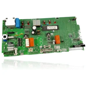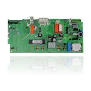


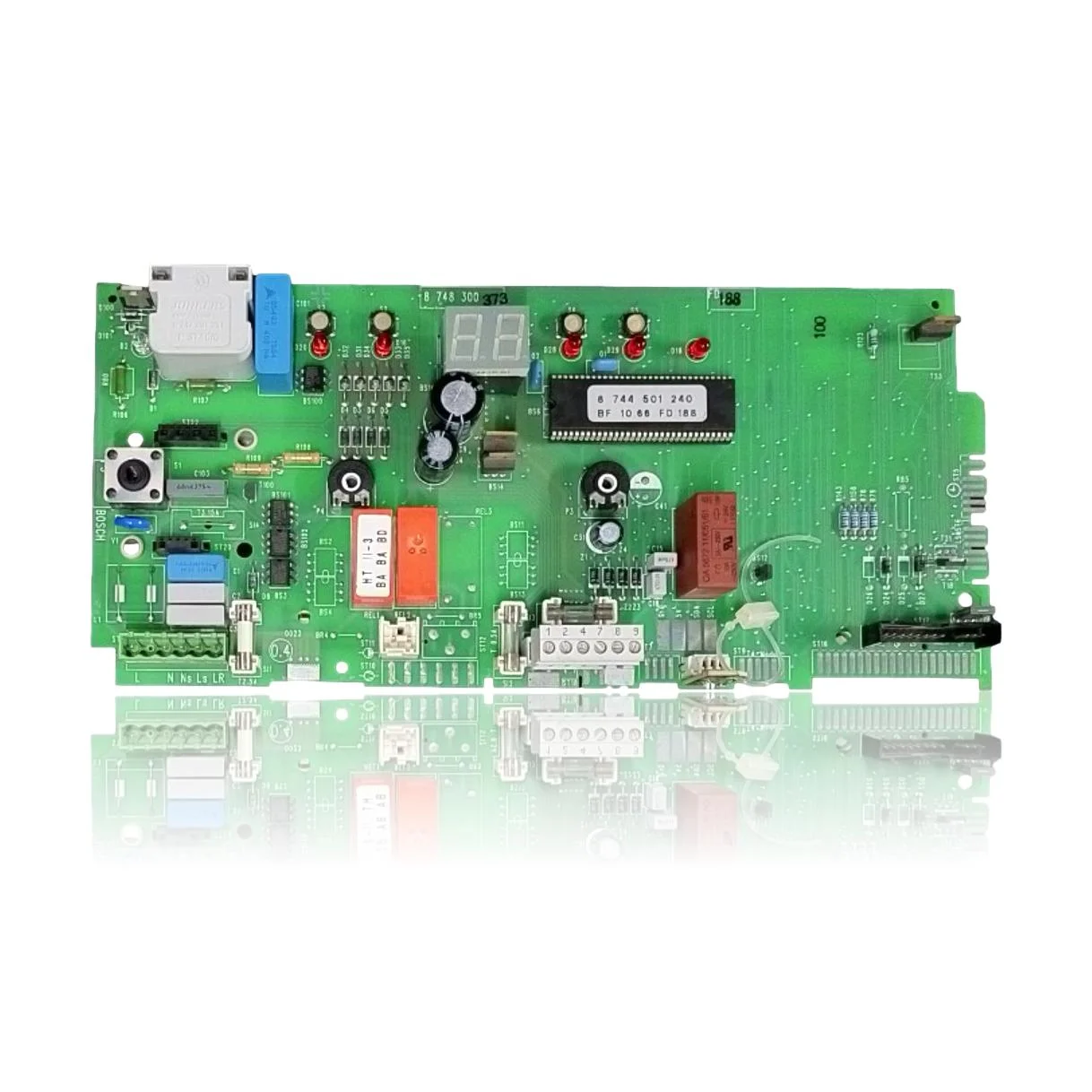
Junkers PCB ZWC24-1MFA23 Ref. 8 748 300 373
If the boiler does not start, locks out, or exhibits erratic behavior, a technical diagnosis must confirm if you need the Bosch Junkers ZWC24-1MFA23 PCB (control board) Ref. 8 748 300 373. This board is the component that controls the ignition, burner modulation, pump, and safety features of the boiler. Users may notice issues such as the fault code F0, which indicates an internal fault, or A8, which signals a communication interruption. This model is compatible with several boilers from the Euromaxx range, including ZWC24 and ZWC28, among others. A technician must confirm through diagnosis whether it is necessary to replace it when these symptoms or fault codes occur.
- Type of part
- PCBs (control boards)
- Status
- Refurbished
- Catalogue reference
- 87483004490
- Warranty
- 1 year
Junkers boilers compatible with reference 87483004490
PCB with reference 87483004490. 12 verified compatibilities: ZWC24-1MF2A23 and ZWC24-1MF2A31.
Proven compatibility
| Boiler model | Family | Verification |
|---|---|---|
| Junkers ZWC24-1MF2A23 | Euromaxx ZWC24 | Contrasted |
| Junkers ZWC24-1MF2A31 | Euromaxx ZWC24 | Contrasted |
| Junkers ZWC24-1MFA23 | Euromaxx ZWC24 | Contrasted |
| Junkers ZWC24-1MFA31 | Euromaxx ZWC24 | Contrasted |
| Junkers ZWC24-1MFK23 | Euromaxx ZWC24 | Contrasted |
| Junkers ZWC24-1MFK31 | Euromaxx ZWC24 | Contrasted |
| Junkers ZWC28-1MF2A23 | Euromaxx ZWC28 | Contrasted |
| Junkers ZWC28-1MF2A31 | Euromaxx ZWC28 | Contrasted |
| Junkers ZWC28-1MFA23 | Euromaxx ZWC28 | Contrasted |
| Junkers ZWC28-1MFA31 | Euromaxx ZWC28 | Contrasted |
| Junkers ZWC28-1MFK23 | Euromaxx ZWC28 | Contrasted |
| Junkers ZWC28-1MFK31 | Euromaxx ZWC28 | Contrasted |
Can't see your model or have questions? The printed reference takes precedence. How to check it · Send us a photo via WhatsApp.
How to check if the ref. 87483004490 is the part for your boiler
The part reference, model, and equipment revision must be verified against the manufacturer's documentation.
- Find the reference printed on the installed part and check whether it matches the catalogue reference 87483004490. If it is not visible, do not identify the part from its shape alone.
- Check the full boiler model on its data plate and look for it in the model associations on this page.
- Compare the connections and physical body with the original part before installation.
- If anything is unclear, send us a photo of the marking via WhatsApp before placing your order.
Symptoms that require diagnosis on the PCB 87483004490
The PCB controls the ignition, modulation, and safety features of the boiler. These are the typical symptoms and what to do:
Common symptoms and faults
- 01
The boiler is completely off: the display does not turn on and the fan does not make any noise when the switch is pressed.
Cause: The power supply stage of the PCB is not cutting off the current to the rest of the circuits.
First, disconnect the main fuse and the power supply to the boiler before replacing the PCB.
- 02
A fault code appears as soon as the boiler is turned on, and it changes every time the boiler is reset.
Cause: It is common for a damaged PCB to provide inconsistent diagnostics because the fault lies in its own control electronics.
Note the code during several consecutive resets; if it does not match each time, the PCB is the main suspect.
- 03
The room thermostat is unable to start the boiler, although the manual ignition does work.
Cause: The circuit of the PCB responsible for receiving the external heat demand has stopped responding.
Do not bridge contacts or power components directly to test them. Request a technician to check the cause according to the model manual and its revision, without bypassing the protections. The symptom or fault code does not confirm on its own that this part is faulty.
- 04
The circulation pump or the gas valve do not activate even though the rest of the ignition cycle seems normal.
Cause: The output relay on the PCB that controls that component may have burned out or become stuck.
Measure with the multimeter if current is reaching the connector of the pump or the valve just when the boiler should activate them.
Junkers fault codes that require diagnosis
| Code | Fault | Technical checks |
|---|---|---|
| F0 | Internal fault/PCB fault. | Internal fault of the Heatronic PCB or the bus; the electronics themselves report the anomaly. Check the voltages and connectors of the PCB, and if the F0 reappears after reset and service tests, replace the PCB. |
| A8 | Communication interrupted between the CAN bus module and the control board. | The loss of CAN communication may be due to a fault in the 24 V/Heatronic PCB (main electronics) or its connector. Check the wiring and BUS module; if the issue persists, replace the PCB (24 V/Heatronic). |
| E9 | The STB has been activated. | It may be triggered by a lack of circulation if the 24 V fuse on the PCB is open (no power to pump/elements), causing overheating. Check the continuity of the fuse on the PCB and restore power before further testing. |
These symptoms can have more than one cause. If your boiler displays a fault code, send it to us via WhatsApp along with a photo of the labeling, and we'll tell you if this is the part.
Data sheet for the Junkers 87483004490 PCB.
- Catalogue reference
- 87483004490
- Uniclima internal SKU
- PLCZWC24-1
- Brand
- Junkers
- Type of part
- PCBs (control boards)
- Units in stock
- 9 units
- Status
- Refurbished
- Warranty
- 1 year
- Shipping
- Delivery time shown at checkout
- Return
- 14 days
Part data and available documentation
Contrast the label codes, PCB, and revision with the installed part; they are not necessarily equivalent references.
- Silkscreened board number
- 8 748 300 373
- EPROM code
- 8 744 501 240 / batch BF 10 66 FD 188
- Ignition relay/transformer code
- HT II-3 / BA BA BD
Frequently asked questions about the PCB 87483004490
What number is printed on the PCB of the ZWC28-1MFK31?
Does this PCB cost the same for the ZWC24-1MFK23 as for the ZWC28-1MFA31?
Does the PCB of the ZWC24-1MFA23 have an identifiable EPROM?
What other identifiable component does the PCB of the ZWC28-1MFA23 have besides the EPROM?
Spare parts related to Junkers Euromaxx ZWC24