

Bosch/Junkers PCB 8 748 301 223 · 8 748 300 449 for ZWC 24 1MFA 23
Application to the exact variant pending confirmation. PCB located in the control panel assembly and wiring of the Junkers Euromaxx ZWC 24, 28-1 MFA family. The lack of ignition, unresponsiveness to buttons, or resets have been associated with another board from that family, the 8744501254; those symptoms do not indicate a fault in this unit.
- Type of part
- PCBs (control boards)
- Status
- Refurbished
- Catalogue reference
- 8 748 300 449
- Warranty
- 1 year
compatible with reference 8 748 300 449
PCB with reference 8 748 300 449. 0 verified compatibilities. There are 3 other models that we are still checking.
Models pending verification
These models are associated with this reference, but we have not finished verifying them yet, so we do not consider them compatibleIf your boiler is one of them, send us a photo of the part you are going to replace and we will verify it before you purchase.
| Bosch/Junkers Junkers Euromaxx ZWC 28-1 MFA | Bosch/Junkers | Unconfirmed |
|---|---|---|
| Bosch/Junkers Junkers ZWC 24 1MFA-1MFK | Bosch/Junkers | Unconfirmed |
| Bosch/Junkers Junkers ZWC 24 1MFA 23 | Bosch/Junkers | Unconfirmed |
Can't see your model or have questions? The printed reference takes precedence. How to check it · Send us a photo via WhatsApp.
How to check if reference 8 748 300 449 is the part for your boiler
The part reference, model, and equipment revision must be verified against the manufacturer's documentation.
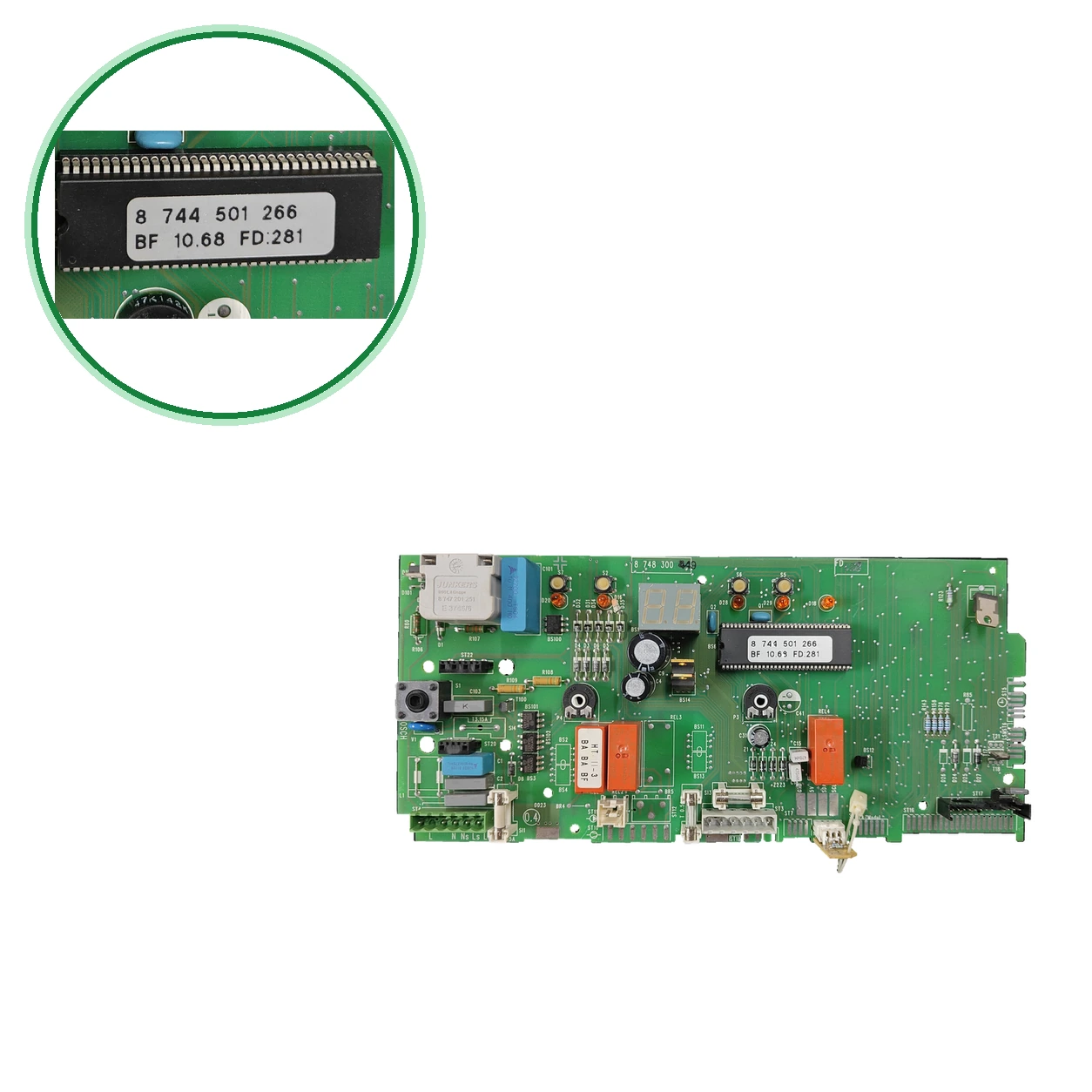
- Look for the marking of the integrated circuit 8 744 501 266 and the code BF 10.68 FD:281 on the PCB.
- The silkscreen on the circuit says 8 748 300 and, handwritten, the suffix 449: 8 748 300 449, the code from the spare parts list (there with a final 0). Our bag has 80748300449.
- The circuit code is 8 748 301 223. Don't just stick with the base 8748300: other Junkers PCBs have suffixes 506, 533, or 149, and 373 is the previous code of 449.
- Check on the rating plate that your boiler is the Junkers ZWC 24 1MFA 23 and compare the fuses: ours uses T3.15A and T1.5A.
- if they match, call us at 911 17 77 77 with the model of your boiler.
Symptoms that require diagnosis on the PCB 8 748 300 449
The PCB controls the ignition, modulation, and safety features of the boiler. These are the typical symptoms and what to do:
Common symptoms and faults
- 01
The boiler does not ignite or does not respond to the buttons.
Cause: To confirm: attribute those symptoms to the PCB 8744501254, another code of the ZWC 24-1 MFA. Check the fuses first.
- 02
Erratic fault codes changing on the display.
Cause: It attributes it to its PCB 8744501254. Have a technician confirm that the cause is the PCB.
- 03
Unexpected resets during operation.
Cause: It attributes it to its PCB 8744501254 and mentions stuck relays or burnt tracks.
- 04
The boiler shuts down or locks out with fault code EA.
Cause: No flame detected: lack of gas, dirty ionization electrode, or poor ionization.
Press reset once if the boiler allows it. If it repeats, have a technician check the gas, the electrode, and its cable.
- 05
The display turns off intermittently or the fault code F0 appears.
Cause: Internal fault of the PCB or loose connections, sometimes due to humidity in the control board enclosure.
Have a technician check the humidity and the connections before replacing the PCB.
- 06
The boiler stops due to overheating and displays fault code E9.
Cause: The safety limiter has been activated: it could be air in the circuit, a blocked pump, or a blown fuse on the PCB.
Bleed the air from the system. If the fault code returns, have a technician check the pump, the fuse, and the sensor.
- 07
The boiler does not ignite and the screen shows EA.
Cause: No flame detected on ignition: there is no ionization current.
Check that the gas valve is open and that there is pressure. If the gas is flowing properly, have a technician check the electrode, its cable, and the PCB.
- 08
The screen shows F0.
Cause: Internal fault of the PCB or its circuit.
Check the contacts, plugs, and ignition and bus cables. If the fault code persists, have a technician replace the PCB.
- 09
The boiler does not receive the commands from the regulator properly and A8 or AC appears.
Cause: Communication interrupted between the bus module, the control unit, and the electronics.
Check the cable between the module and the control board. If the cable is fine, have a technician check the module or the PCB.
- 10
The boiler stops heating and the screen shows E9.
Cause: The safety limiter (STB) has been activated due to excessive temperature.
Check that the pump is circulating, bleed the system, and check the fuse on the PCB. If the fault code returns, have a technician check it.
- 11
On the screen, CC or E2 appears: the PCB is not reading a sensor correctly.
Cause: External sensor or interrupted flow sensor or short-circuited.
Check the affected sensor and its cable. If the sensor and the cable are fine, have a technician check it.
Códigos de error Bosch/Junkers que requieren diagnóstico
| Code | Fault | Technical checks |
|---|---|---|
| EA | There is no ionization current: the boiler does not detect the flame and shuts down or locks out. | Press reset once if the boiler allows it. If it repeats, have a technician check the gas, the ionization electrode, and its cable. If all that is fine, it points to the PCB. |
| E9 | Overheating: the safety limiter has been activated. | Check that there is no air in the system and that the flow sensor is properly connected. If the fault code returns, have a technician check the pump and the fuse on the PCB. |
| F0 | Internal fault of the PCB or its connections. | Check the humidity and the connections of the control board box before replacing it. If the fault code persists, the PCB is the suspected part: have it checked by a technician. |
| FA | It continues to detect flame after closing the gas. | Have a technician check the wiring of the gas valve and the electrode. If the wiring is fine, it points to the PCB. |
| E2 | The heating flow NTC sensor is interrupted or short-circuited. | Check the flow sensor and its cable. If the sensor and the cable are fine, have a technician check the PCB. |
| A7 | The NTC sensor for domestic hot water is interrupted or short-circuited. | Check the domestic hot water sensor and its cable. If the sensor and the cable are fine, have a technician check the PCB. |
| A8 | Communication interrupted between the bus module and the control unit. | Check the cable between the bus module and the control unit or the regulator. If the cable is fine, the module or the PCB may be faulty: have a technician check it. |
| AC | Electrical interruption between the plug module and the Heatronic electronics. | Check the cable between the module and the PCB. If the cable is fine, the fault points to the control board: have a technician check it. |
| CC | The PCB does not detect the outdoor temperature sensor. | Check the outdoor sensor and its cable. It only appears when there is an outdoor sensor or bus regulator installed. |
| d3 | Bornes 8-9 open: the bridge or the thermostat connector is missing. | Check the terminal strip 8-9 and the jumper before suspecting the PCB. |
| AA | Excessive temperature difference between the heating supply and the domestic hot water. | Check the heating and domestic hot water sensors and if there is scale in the heat exchanger. If the sensors are fine, have a technician check it. |
| b1 | Encoder connector on the PCB poorly mounted or defective. | Check that the encoder connector is properly mounted and measure it. If it is fine and the fault code persists, the PCB is the suspect. |
These symptoms can have more than one cause. If your boiler displays a fault code, send it to us via WhatsApp along with a photo of the labeling, and we'll tell you if this is the part.
Technical sheet: Bosch/Junkers 8 748 300 449
- Catalogue reference
- 8 748 300 449
- Uniclima internal SKU
- PLC240
- Brand
- Bosch/Junkers
- Type of part
- PCBs (control boards)
- Units in stock
- 7 units
- Status
- Refurbished
- Warranty
- 1 year
- Shipping
- Delivery time shown at checkout
- Return
- 14 days
Part data and available documentation
Contrast the label codes, PCB, and revision with the installed part; they are not necessarily equivalent references.
- Inventory — Fuse, subcomponent
- T3.15A T1.5A
- Inventory — Application indicated in inventory
- ZWC 24 1MFA 23
- Printed PCB silkscreen
- 8 748 300
- Handwritten suffix on PCB
- 449
- Stock code
- 80748300449
- Identification — Marked code
- 8 744 501 266
- Identification — Marked code
- BF 10.68 FD:281
- Inventory data — Fuse, subcomponent
- T3.15A
- Inventory data — Fuse, subcomponent
- T1.5A
- Inventory data — Application indicated in inventory
- ZWC 24 1MFA 23
- Pending applications to verify
- ZWC 24 1MFA 23 — compatibility noted; pending confirmation by variant. Contrast 24/10/2026: Bosch ETK relates the PCB8 748 300 449 0 with Euromaxx ZWC28-1MFA23S2800, product 7716704005, row 4. The same set prescribes coding plug 8 714 411 176 0 (row 5). The unit has another program/coding marking and the warehouse note indicates ZWC24; that configuration needs to be verified before certifying the application of the set. The match of the PCB does not translate into full compatibility.
- To confirm: Text about another board from the family (8744501254), not an official table.
- To confirm: Junkers Euromaxx ZWC 28-1 MFA — 1 origin: spare parts list of the family (copy in a blog), code 8 748 300 449
- To confirm: Junkers ZWC 24 1MFA-1MFK — 1 origin: from with the code 8748300449
- Do not confuse: 8744501254 — Junkers ZWC24-1MFA PCB — Another code, not the one for this PCB
- Do not confuse: 8748300506 — Junkers PCB ZWC24-1MFA; a breakdown of the printed circuit board ZWSE-4 — Same base 8748300, suffix 506, not 449.
- Do not confuse: 8748300533 — ZWC 24 electronic PCB — Same base 8748300, suffix 533 and not 449.
- Do not confuse: 8748300149 — Junkers PCB "V2", alongside 8748301102 — It looks like 8 748 300 449, but the suffix is 149.
- In the pages we have read, 8 744 501 266 and BF 10.68 FD:281 do not appear, only 8 748 301 223. Compare at least 8 748 300 449 and 8 744 501 266.
- To confirm: The 8 748 300 449 is listed as a PCB in the spare parts list for the Euromaxx ZWC 24, 28-1 MFA, and it is referred to as "base plate" and is not counted. The 8 748 301 223 is only mentioned. The codes and the boiler are confirmed.
- Pending registered applications to confirm by model, variant, or programming: Junkers ZWC 24 1MFA 23.
Frequently asked questions: PCB 8 748 300 449
Where is the code for this PCB and what does each one mean?
Is it compatible with my Junkers ZWC 24 1MFA 23?
What does the spare parts list say about 8 748 300 449?
Is it compatible with the ZWC 28-1 MFA or the ZWC 24 1MFA-1MFK?
Is it the same as 8744501254, 8748300506, 8748300533, or 8748300149?
What symptoms are attributed to the boards of this family and what should I check beforehand?
Who should install the PCB and where does it go?