

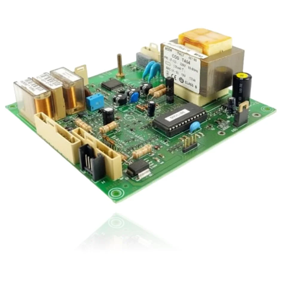
Beretta Super Meteo Turbo 20/24 I PCB (control board)
The Beretta Super Meteo Turbo 20/24 I PCB is the control unit that manages the ignition, burner modulation, pump, and safety features of the boiler. If this part fails, the boiler may not start, become locked, or operate erratically. It is compatible with several models, such as the Super Meteo Turbo 20 I, 24 I, 20 I AG, and 24 I AG, among others. A technician must confirm through diagnosis whether it needs to be replaced when these symptoms are present, as its malfunction affects the performance of the boiler.
- Type of part
- PCBs (control boards)
- Status
- Refurbished
- Catalogue reference
- R9179
- Warranty
- 1 year
Beretta boilers compatible with reference R9179
PCB with reference R9179. Five confirmed compatibilities: Super Meteo Turbo 20 I (680423) and Super Meteo Turbo 24 I (680433).
Proven compatibility
| Boiler model | Family | Verification |
|---|---|---|
| Beretta Super Meteo Turbo 20 I (680423) | Super Meteo Turbo | Contrasted |
| Beretta Super Meteo Turbo 24 I (680433) | Super Meteo Turbo | Contrasted |
| Beretta Super Meteo Turbo 20 I AG (680443) | Super Meteo Turbo | Contrasted |
| Beretta Super Meteo Turbo 24 I AG (680453) | Super Meteo Turbo | Contrasted |
| Beretta Super Meteo Turbo Sealed Chamber 20I/24I | Super Meteo Turbo | Contrasted |
Can't see your model or have questions? The printed reference takes precedence. How to check it · Send us a photo via WhatsApp.
How to check if ref. R9179 is the part for your boiler
The part reference, model, and equipment revision must be verified against the manufacturer's documentation.
- Find the reference printed on the installed part and check whether it matches the catalogue reference R9179. If it is not visible, do not identify the part from its shape alone.
- Check the full boiler model on its data plate and look for it in the model associations on this page.
- Compare the connections and physical body with the original part before installation.
- If anything is unclear, send us a photo of the marking via WhatsApp before placing your order.
Symptoms that require diagnosis on the PCB R9179
The PCB controls the ignition, modulation, and safety features of the boiler. These are the typical symptoms and what to do:
Common symptoms and faults
- 01
The boiler is unresponsive, it is completely off and no lights are turning on.
Cause: The transformer or the fuse on the PCB does not supply the necessary current.
Measure with a multimeter if there is current at the transformer output and check that the fuse is in good condition before replacing the PCB.
- 02
The fuse blows immediately after replacing it.
Cause: There is a short circuit in some component connected to the PCB, not in the PCB itself.
Disconnect the pump and the gas valve, and check if the fuse holds before considering that the PCB is faulty.
- 03
The boiler briefly ignites the burner and then locks out.
Cause: The PCB does not activate the gas relay for the necessary time to confirm ignition.
Check that the ignition electrodes and the ionization cable are in good condition before blaming the PCB.
- 04
The ignition indicator flashes or stays on without any apparent reason.
Cause: An internal fault in the PCB generates an error signal that does not always indicate a real external problem.
Note the blinking code or pattern and consult the boiler manual to rule out other causes before replacing the PCB.
These symptoms can have more than one cause. If your boiler displays a fault code, send it to us via WhatsApp along with a photo of the labeling, and we'll tell you if this is the part.
Data sheet for the Beretta R9179 PCB.
- Catalogue reference
- R9179
- Uniclima internal SKU
- PECBK2312
- Brand
- Beretta
- Type of part
- PCBs (control boards)
- Units in stock
- 1 unit
- Status
- Refurbished
- Warranty
- 1 year
- Shipping
- Delivery time shown at checkout
- Return
- 14 days
Part data and available documentation
Contrast the label codes, PCB, and revision with the installed part; they are not necessarily equivalent references.
- Transformer - primary
- 220V, 48-60Hz, 130mA (ACEM Italy transformer, code TA04)
- Transformer - secondary
- 18V, 12VA, Class B (ACEM Italy transformer, cod. TA04)
- Fuse
- 100mAT (100mA timed)
- Transformer manufacturer
- ACEM Italy
Frequently asked questions about the R9179 PCB.
Is this PCB suitable for the Beretta Super Meteo Turbo 24 I AG?
What transformer does this PCB for the Super Meteo Turbo 20 I use?
What fuse does the PCB of the Beretta Super Meteo Turbo use?
Is this PCB also suitable for the Super Meteo Turbo 20 I AG?