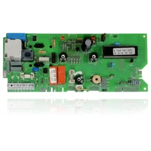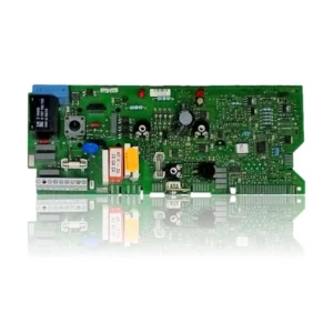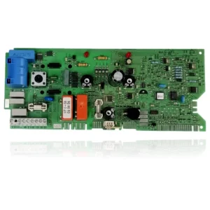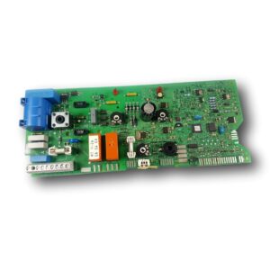


Bosch Junkers PCB ZWA 24-1AM23 Ref. 8748300488
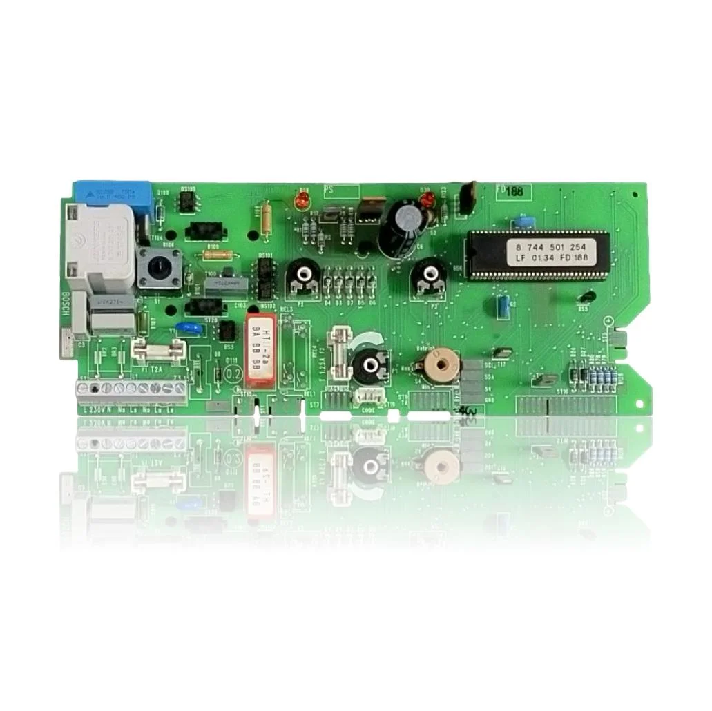
Bosch Junkers PCB ZWA 24-1AM23 Ref. 8748300488, component that controls the ignition, burner modulation, pump, and safety features of the boiler. When it fails, the boiler may not start, become locked, or exhibit erratic operation, which is indicated by the reset button flashing at 1 Hz or 4 Hz. It is compatible with models such as ZWA 24-1 AM 23, ZWA 24-1 AM 31, ZWA 24-1 KM 23, among others. A technician must confirm through diagnosis whether it needs to be replaced upon detecting symptoms of malfunction or frequent lockouts.
- Type of part
- PCBs (control boards)
- Status
- Refurbished
- Catalogue reference
- 8748300488
- Warranty
- 1 year
Junkers boilers compatible with reference 8748300488
PCB with reference 8748300488. Four confirmed compatibilities: ZWA 24-1 AM 23 and ZWA 24-1 AM 31.
Proven compatibility
| Boiler model | Family | Verification |
|---|---|---|
| Junkers ZWA 24-1 AM 23 | Junkers Eurosmart ZWA 24 | Contrasted |
| Junkers ZWA 24-1 AM 31 | Junkers Eurosmart ZWA 24 | Contrasted |
| Junkers ZWA 24-1 KM 23 | Junkers Eurosmart ZWA 24 | Contrasted |
| Junkers ZWA 24-1 KM 31 | Junkers Eurosmart ZWA 24 | Contrasted |
Can't see your model or have questions? The printed reference takes precedence. How to check it · Send us a photo via WhatsApp.
How to check if ref. 8748300488 is the part for your boiler
The part reference, model, and equipment revision must be verified against the manufacturer's documentation.
- Find the reference printed on the installed part and check whether it matches the catalogue reference 8748300488. If it is not visible, do not identify the part from its shape alone.
- Check the full boiler model on its data plate and look for it in the model associations on this page.
- Compare the connections and physical body with the original part before installation.
- If anything is unclear, send us a photo of the marking via WhatsApp before placing your order.
Symptoms that require diagnosis on the PCB 8748300488
The PCB controls the ignition, modulation, and safety features of the boiler. These are the typical symptoms and what to do:
Common symptoms and faults
- 01
The boiler does not turn on: there is no display, the fan does not make any sound, nothing.
Cause: The PCB does not distribute power to the ignition system.
Check the main fuse of the boiler and the circuit breaker of the installation before declaring the PCB faulty.
- 02
It turns on, tries to start, and gets locked with a different fault code each time it is reset.
Cause: The control logic of the PCB is giving incorrect diagnostics because the fault lies in its electronics.
Note the code in each attempt; if it does not repeat, suspect the PCB before an external component.
- 03
It does not respond to either the control or the room thermostat, although in manual mode the boiler does ignite.
Cause: The circuit of the PCB that processes the external heat demand signal is faulty.
Do not force, hit, or bridge the component. Request a technical check according to the equipment manual before deciding on its replacement.
- 04
It works well for a while and then turns off or restarts by itself for no apparent reason.
Cause: It could be a thermal fault in the PCB, with components that degrade when heated.
Check if the cut always occurs after the same operating time; that pattern indicates a PCB fault due to heat.
Junkers fault codes that require diagnosis
| Code | Fault | Technical checks |
|---|---|---|
| The reset button flashes at 1 Hz (once per second) | Lockout due to ignition/overheating/internal fault group. | The control board (Eurotronic/PCB) may fail in ignition/flame management or in powering sensors/actuators, causing this blockage. Check 230 V at ST2, signals/outputs at ST16, and if peripherals and wiring are correct, replace the board. |
| The reset button flashes at 4 Hz (four times per second) | Lockout due to flue evacuation/safety group or associated sensors. | A defect in the control board can prevent the correct management/reading of the fan, pressure switch, NTC, or the encoder connector, triggering the 4 Hz. Check connectors ST16/ST1, power supply to the fan, and continuity of sensors; if everything is okay and it persists, the board is the probable cause. |
These symptoms can have more than one cause. If your boiler displays a fault code, send it to us via WhatsApp along with a photo of the labeling, and we'll tell you if this is the part.
Data sheet for the Junkers 8748300488 PCB.
- Catalogue reference
- 8748300488
- Uniclima internal SKU
- PLCZWA24-1
- Brand
- Junkers
- Type of part
- PCBs (control boards)
- Units in stock
- 2 units
- Status
- Refurbished
- Warranty
- 1 year
- Shipping
- Delivery time shown at checkout
- Return
- 14 days
Part data and available documentation
Contrast the label codes, PCB, and revision with the installed part; they are not necessarily equivalent references.
- Manufacturer
- Bosch
- EPROM chip code
- 8 744 501 254
- Chip batch
- LF 01.34 FD 188
- Supply voltage
- 230V
- Fuse
- T 1.25A
Frequently asked questions about the PCB 8748300488
Does this Bosch PCB work for the Junkers ZWA 24-1 AM 23?
Who manufactures the PCB for the Junkers ZWA 24-1 AM 23?
What voltage and fuse does the PCB of the ZWA 24-1 AM 23 need?
When should this PCB be replaced in a Junkers ZWA 24-1 AM 23 boiler?
What fault codes are documented for this PCB?
Is the reference PLCZWA24-1 valid for this PCB?
Spare parts related to Junkers Junkers Eurosmart ZWA 24