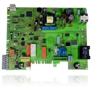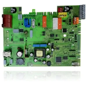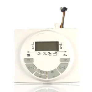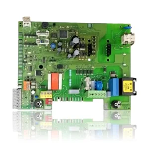


Junkers Cerapur/CerapurComfort PCB ZWBC Ref. 8748300923
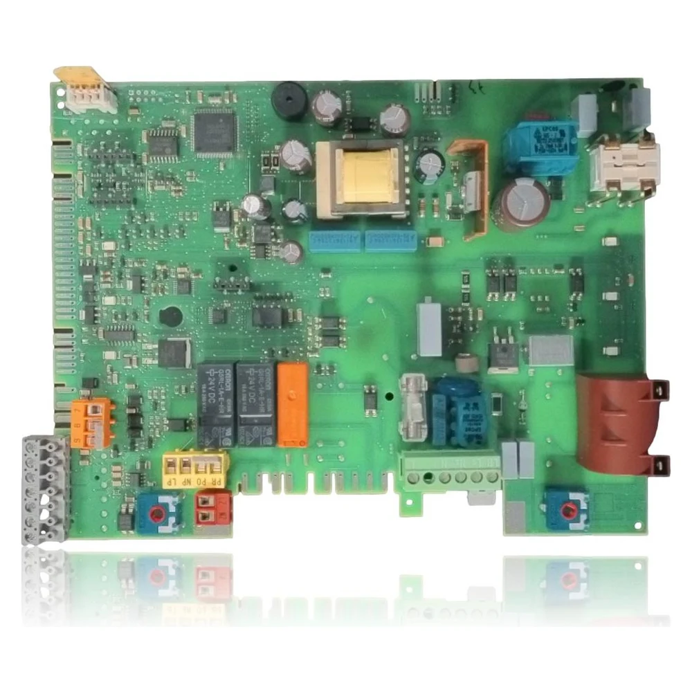
Main PCB Heatronic 3 for the Junkers Cerapur Comfort ZWBC 30-2 C 23. It controls ignition, fan, pump, modulation, and safety features. This refurbished unit replaces the original when there are internal faults (F0), data errors (b2), or communication issues (A8), after verifying sensors, wiring, and the coded connector.
- Type of part
- PCBs (control boards)
- Status
- Refurbished
- Catalogue reference
- 8748300923
- Warranty
- 1 year
Junkers boilers compatible with reference 8748300923
PCB with reference 8748300923. 12 verified compatibilities: ZWBC 24-2C and ZWBC 25-2C.
Proven compatibility
| Boiler model | Family | Verification |
|---|---|---|
| Junkers ZWBC 24-2C | Cerapur Comfort ZWBC (2C) | Contrasted |
| Junkers ZWBC 25-2C | Cerapur Comfort ZWBC (2C) | Contrasted |
| Junkers ZWBC 28-2C | Cerapur Comfort ZWBC (2C) | Contrasted |
| Junkers ZWBC 30-2C | Cerapur Comfort ZWBC (2C) | Contrasted |
| Junkers ZWBC 30-2 C 23 (7716010270) | Cerapur Comfort | Contrasted |
| Junkers ZWBC 30-2 C 31 (7716010286) | Cerapur Comfort | Contrasted |
| Junkers ZWBC 25-2 C 23 (7716010269) | Cerapur Comfort | Contrasted |
| Junkers ZWBC 25-2 C 31 (7716010285) | Cerapur Comfort | Contrasted |
| Junkers ZWBC 24-2 C 23 (7 736 900 799) | Cerapur | Contrasted |
| Junkers ZWBC 24-2 C 31 (7 736 900 801) | Cerapur | Contrasted |
| Junkers ZWBC 28-2 C 23 (7 736 900 800) | Cerapur | Contrasted |
| Junkers ZWBC 28-2 C 31 (7 736 900 802) | Cerapur | Contrasted |
Can't see your model or have questions? The printed reference takes precedence. How to check it · Send us a photo via WhatsApp.
How to check if ref. 8748300923 is the part for your boiler
The part reference, model, and equipment revision must be verified against the manufacturer's documentation.
Symptoms that require diagnosis on the PCB 8748300923
The PCB controls the ignition, modulation, and safety features of the boiler. These are the typical symptoms and what to do:
Common symptoms and faults
- 01
The boiler is locking with F0 or b2 and does not start.
Cause: Internal fault in the Heatronic 3 electronics
Check 230 V~, fuses, and connectors; if the issue persists, the PCB is likely faulty.
- 02
Intermittent communication losses (A8) with display/thermostat
Cause: Fault in eBUS or in the communication stage of the PCB.
Try with another eBUS/peripheral cable; if it remains the same, the PCB may be defective.
- 03
The fan or pump does not operate despite demand.
Cause: Power output relay on PCB damaged
Power the actuator externally and check the continuity of the harness; if the actuator works outside, check the PCB.
- 04
NTC errors (A7/E2) with new sensors
Cause: Damaged analog measurement channels on the PCB.
Measure NTC resistances and continuity; if correct, the input of the PCB is failing.
- 05
EA with spark present and correct gas
Cause: Fault in the ionization detection stage
Check electrodes/cables and return; if everything is fine, suspect the PCB.
Junkers fault codes that require diagnosis
| Code | Fault | Technical checks |
|---|---|---|
| F0 | Internal fault | Check electrical contacts, ignition cables, and bus; if the issue persists, replace the PCB (Heatronic 3). |
| b2 | Internal data error | Technician intervention; if the issue is not resolved by checking connections and resetting, the PCB may be damaged. |
| A8 | eBUS communication interrupted | Check the eBUS cable and peripherals. If the bus and the display are correct, there is likely a fault in the main electronics. |
| b1 | Encoded connector not detected | Connect/transfer the coded connector and its wires. If it is present and the fault persists, check the socket/PCB. |
| EA | Flame not detected | Check gas, electrodes, and pressures. If the spark and gas are correct but there is no ionization signal, assess the control stage on the PCB. |
| C6 | The fan is not working. | Check the fan and its wiring. If the fan is properly powered and operational outside the PCB, suspect the output/relay of the PCB. |
| E2 | Faulty supply sensor | Check NTC and cable. If erratic reading is confirmed and the sensor is correct, possible fault in the input channel on the PCB. |
| A7 | Faulty domestic hot water sensor | Check continuity/derivations of the NTC ACS and its harness. If the sensor is fine, check the analog input of the PCB. |
| E9 | Temperature limiter (STB) tripped | Bleed, check the pump, flow rate, and fuses of the PCB. If the hydraulic circuit is correct, confirm the integrity of the PCB. |
| d3 | External controller/TB1 active or without jumper 8–9 | Do not bridge contacts or power components directly to test them. Request a technician to check the cause according to the model manual and its revision, without bypassing the protections. The symptom or fault code does not confirm on its own that this part is faulty. |
| F7/FA | Anomalous/persistent ionization signal | Check the electrodes/cables and moisture in the Heatronic. If everything is correct, assess the detection electronics on the PCB. |
These symptoms can have more than one cause. If your boiler displays a fault code, send it to us via WhatsApp along with a photo of the labeling, and we'll tell you if this is the part.
Data sheet for the Junkers 8748300923 PCB.
- Catalogue reference
- 8748300923
- Uniclima internal SKU
- PECZWBC24
- Brand
- Junkers
- Type of part
- PCBs (control boards)
- Units in stock
- 7 units
- Status
- Refurbished
- Warranty
- 1 year
- Shipping
- Delivery time shown at checkout
- Return
- 14 days
Part data and available documentation
Contrast the label codes, PCB, and revision with the installed part; they are not necessarily equivalent references.
- Control system
- Bosch Heatronic 3 (main PCB)
- OEM Ref.
- 8748300923 (also 87483009230 in catalogs)
- Equivalent references
- 8748300714, 8748300829, 874183005910, 87483008810, 87483006760, 87483005910
- Compatibility confirmed
- Cerapur/CerapurComfort ZWBC 24/25/28/30-2 C (23 and 31); includes ZWBC 30-2 C 23
- Power relays
- Omron 24 VDC (according to usual silkscreen)
- Dimensions (REMLE packaging)
- Approximately 29 × 22 × 12 cm
- Component manufacturer
- Bosch Thermotechnik (Junkers/Bosch)
- Disconnect 230 V~ and close the gas valve before opening the boiler.
- Electrostatic discharge: use an ESD wrist strap when handling the PCB.
- Check and, if necessary, replace gaskets in single-piece housings/modules that can be opened.
- Transfer the coded connector from the old PCB; without it, b1 will appear.
- After the change, check Heatronic 3 parameters (power, hysteresis, functions 1.A, 2.x).
- Bleed the circuit and the condensate siphon before starting up.
- Check for the absence of moisture in the PCB; dry before powering up.
- Any intervention must be carried out by qualified personnel in gas and electricity.
Manuals and technical documentation
Official documentation of the boiler, useful for locating the part and cross-referencing the fault codes.
- Junkers ZWBC 30-2C manual (PDF) Document © Junkers, provided as a technical reference.
Frequently asked questions about the PCB 8748300923
Does this PCB work for my ZWBC 30-2 C 23 in Spain?
Do I need to program anything after replacing it?
I see b1 after the change, what does it mean?
Why do some catalogs show 87483009230?
I have EA, is it always the PCB?
Spare parts related to Junkers Cerapur Comfort ZWBC (2C)