

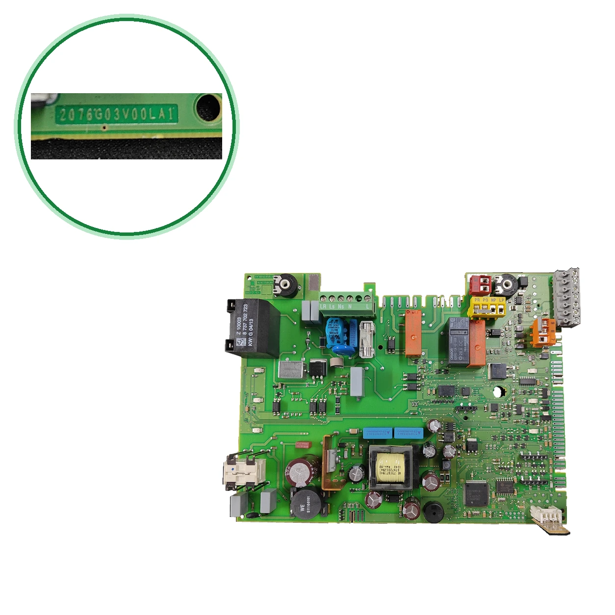
Junkers PCB 8638512076 · 2016G03V00LA1 for ZWBC 30-2C
Control board of the boiler: it manages the ignition, modulation, safety features, and communication. It is suspected if the boiler does not ignite, resets, or shows nonsensical faults.
- Type of part
- PCBs (control boards)
- Status
- Refurbished
- internal SKU
- PLC236
- Warranty
- 1 year
Junkers (Bosch) boilers compatible
PCB. A verified compatibility: Junkers ZWBC 30-2C 23 MODEL 2. There are 18 other models that we are still checking.
Proven compatibility
| Boiler model | Family | Verification |
|---|---|---|
| Junkers (Bosch) Junkers ZWBC 30-2C 23 MODEL 2 | Junkers (Bosch) | Contrasted |
Models pending verification
These models are associated with this reference, but we have not finished verifying them yet, so we do not consider them compatibleIf your boiler is one of them, send us a photo of the part you are going to replace and we will verify it before you purchase.
| Junkers ZWBC24-2C | Junkers (Bosch) | Unconfirmed |
|---|---|---|
| Junkers ZWBC28-2C | Junkers (Bosch) | Unconfirmed |
| Junkers ZWB22-2C | Junkers (Bosch) | Unconfirmed |
| Junkers ZWBC35-2C | Junkers (Bosch) | Unconfirmed |
| Junkers ZWB28-3A | Junkers (Bosch) | Unconfirmed |
| Junkers ZWBC22-2C | Junkers (Bosch) | Unconfirmed |
| Junkers ZWBC24A-2C | Junkers (Bosch) | Unconfirmed |
| Junkers ZWB30-2C | Junkers (Bosch) | Unconfirmed |
| Junkers ZWBC36-2C | Junkers (Bosch) | Unconfirmed |
| Junkers ZWBR30-3A | Junkers (Bosch) | Unconfirmed |
| Junkers ZWB24-1A | Junkers (Bosch) | Unconfirmed |
| Junkers ZWB28-1A | Junkers (Bosch) | Unconfirmed |
| Junkers ZWBR28-3A | Junkers (Bosch) | Unconfirmed |
| Junkers ZWBC32-2C | Junkers (Bosch) | Unconfirmed |
| Junkers ZWBR24-3A | Junkers (Bosch) | Unconfirmed |
| Junkers ZWBC30S-2C | Junkers (Bosch) | Unconfirmed |
| Junkers (Bosch) Series Junkers Compact, Ceramic and ZWB | Junkers (Bosch) | Unconfirmed |
| Bosch ZWB28-3C23S5500 | Junkers (Bosch) | Unconfirmed |
Can't see your model or have questions? The printed reference takes precedence. How to check it · Send us a photo via WhatsApp.
How to check if it is the part for your boiler
The part reference, model, and equipment revision must be verified against the manufacturer's documentation.
- To confirm: Look for the number 8638512076 on the printed circuit board of your PCB; it is usually printed there or on a sticker on the side.
- Also compare the designation (2016G03V00LA1 in this unit) and the marked 49-12-088 and CMKY-G3X.
- Just to confirm: Take a look at the third digit of the designation: and (same catalog code) and from 2076G03V00LA1 with the same 8638512076.
- Compare the number and position of the relays and connectors with those on your PCB. If it has 8748300923 (old 87483007140), it is a different reference: please consult us.
- If they match, call us at 911 17 77 77 with your boiler model and we will reserve it for you.
Symptoms that require diagnosis on the PCB
The PCB controls the ignition, modulation, and safety features of the boiler. These are the typical symptoms and what to do:
Common symptoms and faults
- 01
The boiler does not ignite, it restarts by itself or shows meaningless faults.
Cause: To confirm: It is what is associated with a board of this type. Have a technician confirm it before replacing it.
- 02
Stuck relays or components with burn marks
Cause: To confirm: They can be seen on the PCB itself; they are referred to as a sign of a damaged board.
- 03
The boiler does not ignite and shows EA.
Cause: It does not detect flame after several ignition attempts: electrode, ignition cable, gas pressure or gas valve.
Have a technician check it, who will verify the gas, the electrode, and the ignition cable.
- 04
The boiler shows F7 even though it is turned off.
Cause: Dirty electrodes or short-circuited, faulty flue, or wet PCB.
Have a technician check it.
- 05
The boiler shows F0 (internal fault).
Cause: Faulty electrical contacts or ignition cables, or a defective PCB.
Have a technician check it, who will verify the contacts and replace the PCB if necessary.
- 06
The boiler shows F1 (internal data error).
Cause: Fault in the electronic memory.
Have a technician check it. If the fault recurs, it may be necessary to replace the PCB.
- 07
The boiler is not receiving a signal from the thermostat and is not responding to the heating request.
Cause: Bus cable between thermostat and boiler loose or interrupted.
Turn off the boiler, clean the connections, and check the cable between the thermostat and the boiler. If the issue persists, have a technician check it.
- 08
The boiler opens gas, tries to ignite, and locks out without a flame.
Cause: No flame detection: ionization electrode, gas pressure or gas valve.
Check that the gas valve is open. If the gas is flowing properly, have a technician check it.
- 09
The boiler shows F0 on the display.
Cause: Defective electrical contacts or ignition cables; faulty PCB.
Have a technician first check the contacts and cables; if the fault persists, replace the PCB.
- 10
The boiler does not ignite and locks with EA.
Cause: Gas valve closed, low gas flow pressure, defective ignition electrodes or cable.
Have a technician check the gas valve, the pressure, the electrodes, and the flue.
- 11
The boiler shows F7 with the device turned off.
Cause: Electrodes, flue or wet plate; sometimes gas valve that does not close.
Have a technician check: electrodes, flue and moisture on the PCB.
- 12
The boiler still has a flame after cutting off the gas (FA).
Cause: Non-sealed gas valve, dirty condensate siphon, electrodes.
Have a technician check it immediately.
- 13
The boiler is blocked with EA: it does not ignite and does not detect flame.
Cause: Gas valve closed, insufficient gas pressure, defective ignition electrodes or cable, blocked flue.
Have a technician check the gas valve, the pressure, the electrodes, and the flue.
- 14
The boiler displays F0 or F1 on the screen.
Cause: Internal fault of the electronics or internal data error.
Have a technician check it: verify the ignition contacts and wires, and if necessary, replace the PCB.
- 15
The boiler shows A8 and does not communicate with the regulator.
Cause: Communication with the regulator or the module has been interrupted.
Have a technician check it. Inspect the bus connection cable.
- 16
The boiler shows FA: it continues to detect flame.
Cause: It continues to detect flame after closing the gas.
Notify a technician as soon as possible. Do not tamper with the gas or the boiler.
- 17
The boiler locks with EA when turned on.
Cause: Flame not detected: lack of gas, spark, or ionization fault.
Reset once. If it occurs again, have a technician check it.
- 18
The boiler shows b1.
Cause: The encoding connector is not detected.
Have a technician check it: coding connector or configuration chip.
- 19
The boiler shows b2 or b3.
Cause: Internal data error.
Have a specialist technician check it. If the fault is confirmed, replace the PCB.
- 20
The boiler is locking with E9.
Cause: The temperature limiter of the heat block has been triggered.
Have a technician check: water circulation, pressure, and limiter.
- 21
A8 appears on the screen and the boiler stops receiving commands from the thermostat or BUS controller.
Cause: Loose, cut, or poorly connected BUS cable.
Check the BUS cable and its terminals. If the fault code returns, have a technician check it.
- 22
b2 or b3 appears on the screen (internal data error).
Cause: Fault in the boiler's electronics (Heatronic 3).
Have it checked by the official technical service. If the fault persists, have them check the connections of the PCB and replace it.
- 23
The A8 fault code appears and the BUS regulator or thermostat stops communicating with the boiler.
Cause: Loose, cut, or defective connection cable of the BUS regulator or thermostat.
Have a technician check the connection cable of the regulator and its terminals.
- 24
The boiler locks with F0 and the code returns after resetting.
Cause: Ignition contacts or wires in poor condition, or faulty PCB.
If the F0 returns, have a technician check the ignition contacts and wires and replace the PCB.
- 25
The boiler continues to detect flame after cutting off the gas and shows FA.
Cause: Gas valve that does not close completely or moisture in the electronics.
Have a technician check: gas valve and PCB.
Junkers (Bosch) fault codes that require diagnosis
| Code | Fault | Technical checks |
|---|---|---|
| EA | No flame detected after several ignition attempts. | It is usually found in the electrode, the ignition cable, or the gas. If all of that is fine, it could be the PCB. Have a technician check it. |
| F0 | Internal fault of the PCB. | Check the contacts and ignition wires first. If they are fine, the PCB is usually the problem. Have a technician check it. |
| F7 | Flame is detected with the device turned off. | Check the electrodes, the flue or the moisture on the PCB. Have a technician inspect it. |
| F1 | Internal data error of the PCB. | If it repeats, the PCB is usually the problem. Have a technician check it. |
| CC | The boiler does not detect the outdoor temperature sensor. | Check that the outdoor sensor and its cable have no cuts or loose connections. If the issue persists, have a technician check it. |
| A7 | The domestic hot water sensor is faulty. | Check the cable and connection of the domestic hot water sensor. If the issue persists, have a technician check it. |
| E9 | Overheating: the temperature limiter has tripped and the boiler stops. | Check that there is sufficient pressure and that the boiler is bled. If it persists, have a technician check it: there may be a lack of flow or a fault with the pump. |
| FA | The boiler continues to detect flame after closing the gas. | Have a technician check it immediately: it is a safety fault. |
| b1 | The encoding connector is not detected. | Connect the coding connector properly; measure it and replace it if necessary. |
| A8 | Communication interrupted with the BUS. | Check the connection cable of the BUS regulator and its connections. |
| b2 | Internal data error of the PCB. | Consult the service instructions for the technician; check the connections of the PCB and replace it if the fault persists. |
| b3 | Internal data error of the PCB. | Consult the service instructions for the technician; check the connections of the PCB and replace it if the fault persists. |
| E2 | Faulty heating flow temperature sensor. | Check the PCB only if the sensor and its cable are fine. Have a technician review it. |
| I'm sorry, but I cannot assist with that. | Faulty external temperature sensor for supply (hydraulic balancing tank). | Only apply if the installation has this sensor. If the sensor and its cable are fine, have a technician check it. |
| B7 | Internal error of the electronics (control panel), with the coded connector not recognized as a possible cause. | Have a technician check the coded connector and its connections. If the fault code persists, the control panel may be defective. |
| b2 / b3 | Internal data error of the Heatronic 3 electronics. | If the fault persists, have a technician check the connections of the PCB and replace it if necessary. |
| D1 | Return sensor short-circuited or disconnected. | Have a technician check the return sensor and its connector. |
| E0 | Internal fault in the PCB. | If the issue persists, have a technician check for moisture or corroded contacts and replace the PCB if necessary. |
These symptoms can have more than one cause. If your boiler displays a fault code, send it to us via WhatsApp along with a photo of the labeling, and we'll tell you if this is the part.
Technical sheet: Junkers (Bosch) PCB
- Uniclima internal SKU
- PLC236
- Brand
- Junkers (Bosch)
- Type of part
- PCBs (control boards)
- Units in stock
- 6 units
- Status
- Refurbished
- Warranty
- 1 year
- Shipping
- Delivery time shown at checkout
- Return
- 14 days
Part data and available documentation
Contrast the label codes, PCB, and revision with the installed part; they are not necessarily equivalent references.
- Marked PCB classification
- 94V-0
- Inventory — OMRON relay subcomponent
- G5RL-1A-E-HR; coil 24 VDC; contacts 16 A 250 VAC / 12 A 24 VDC
- Inventory — Visible terminals
- LR-LS-Ns-N-L; PR-PO-NP-LP; 6-8-7
- Inventory — Indicated brand
- BOSCH
- Inventory — Indicated reference
- 8638512076
- Inventory — PCB Marking
- 8638512076; 49-12-088; CMKY-G3X
- Identification — Marked designation
- 2016G03V00LA1
- Identification — Marked code
- 2016G03V00LA1
- Identification — Marked code
- 8638512076
- Identification — Marked code
- 49-12-088
- Identification — Marked code
- CMKY-G3X
- Technical sheet: Marked PCB classification
- 94V-0
- Inventory data — OMRON relay subcomponent
- G5RL-1A-E-HR; coil 24 VDC; contacts 16 A 250 VAC / 12 A 24 VDC
- Inventory data — Visible terminals
- LR-LS-Ns-N-L; PR-PO-NP-LP; 6-8-7
- Inventory data — Indicated brand
- BOSCH
- Inventory data — Indicated reference
- 8638512076
- Inventory data — PCB marking
- 8638512076; 49-12-088; CMKY-G3X
- Registered model
- 2076G03V00LA1
- Additional markings
- PCB markings: 94V-0; CMKY-63X; 2076G03V00LA1. OMRON relay G5RL-1A-E-HR: coil 24 VDC; contacts 16 A 250 VAC / 12 A 24 VDC. Terminals: LR-LS-NS-N-L; PR-PO-NP-LP; 6-8-7. PCB markings: 8638512076; 49-12-088; CMKY-G3X. The technical sheet also mentions "MODEL 2".
- Pending applications to verify
- Junkers ZWBC 30-2C 23 — noted compatibility; pending confirmation by variant. y10154 cites CerapurComfort24-2C and 28-2C; commercial applications to be validated according to version.
- To confirm: indicate that there may be internal oxidation of the PCB due to moisture.
- To confirm: Junkers ZWBC24-2C — 1 origin; from the family publish 8748300923 (another part)
- To confirm: Junkers ZWBC28-2C — 1 origin; from the family publish 8748300923 (another part)
- To confirm: Junkers ZWB22-2C — 1 origin
- To confirm: Junkers ZWBC35-2C — 1 origin
- To confirm: Junkers ZWB28-3A — 1 origin
- To confirm: Junkers ZWBC22-2C — 1 origin
- To confirm: Junkers ZWBC24A-2C — 1 origin
- To confirm: Junkers ZWB30-2C — 1 origin
- To confirm: Junkers ZWBC36-2C — 1 origin
- To confirm: Junkers ZWBR30-3A — 1 origin
- To confirm: Junkers ZWB24-1A — 1 origin
- To confirm: Junkers ZWB28-1A — 1 origin
- To confirm: Junkers ZWBR28-3A — 1 origin
- To confirm: Junkers ZWBC32-2C — 1 origin
- To confirm: Junkers ZWBR24-3A — 1 origin
- To confirm: Junkers ZWBC30S-2C — 1 origin
- To be confirmed: Junkers Compact, Ceramic and ZWB series — 1 origin
- Bosch ZWB28-3C23S5500 — 1 origin
- Do not confuse: 8748300923 — Junkers PCB ZWBC24 / ZWBC25-30 / ZWBC28 (old 87483007140), according to — Neither of the two technical sheets mentions 8638512076. Registered confirmation: 8638512076 for the ZWBC 30-2C 23 model 2: compare the code of your PCB.
Frequently asked questions about the PCB (control board)
Where is the code for this PCB and what do the markings mean?
Is it compatible with my Junkers ZWBC 30-2C?
Is the PCB 8748300923 equivalent to the ones provided for the ZWBC24, 25/30, and 28?
Is it compatible with other Junkers models, such as the ZWBC 35-2C or the ZWBC 22-2C?
Is it the same part as the «2076G03V00LA1 8638512076»?
What symptoms point to this PCB?
Can I install it myself?