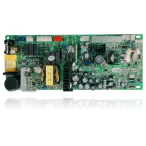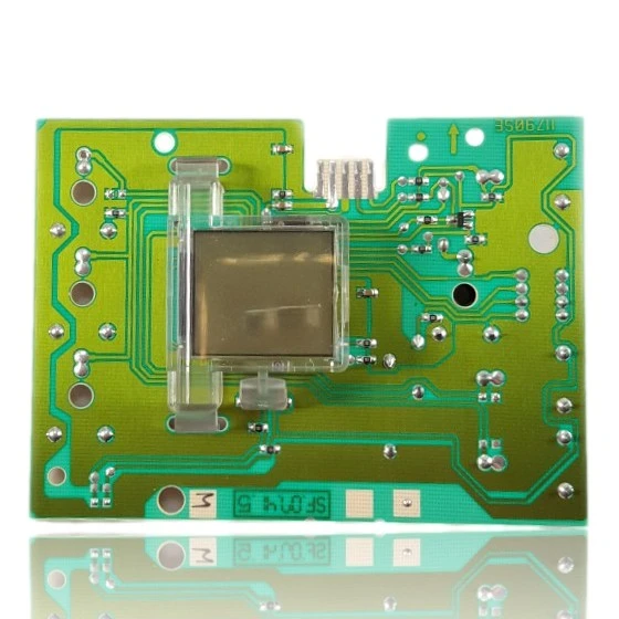
Vaillant PCB Control MAG ES PT 14 2 0 H R1 Ref. 130853
The Vaillant Control PCB MAG ES PT 14 2 0 H R1 Ref. 130853 is a component that controls the ignition, burner modulation, pump, and safety features of the boiler. If it fails, the boiler may not start, become locked, or exhibit erratic behavior. This board is compatible with models such as MAG ES PT 14-2/0 H R1, MAG 14-2/0, MAG 11-2/0, among others in the MAG range. It should be replaced when errors such as F.11, F.12, F.05, or F.06 occur.
VAT included
Consult via WhatsAppVaillant boilers compatible with reference 130853
PCB with reference 130853. Seven confirmed compatibilities: MAG ES PT 14-2/0 H R1 and MAG 14-2/0.
Proven compatibility
| Boiler model | Family | Verification |
|---|---|---|
| Vaillant MAG ES PT 14-2/0 H R1 | MAG 14 | Contrasted |
| Vaillant MAG 14-2/0 | MAG 14 | Contrasted |
| Vaillant MAG 14-2/0 R1 | MAG 14 | Contrasted |
| Vaillant MAG 11-2/0 | MAG 11 | Contrasted |
| Vaillant MAG 11-2/0 R1 | MAG 11 | Contrasted |
| Vaillant MAG 17-2/0 | MAG 17 | Contrasted |
| Vaillant MAG 17-2/0 A R1 | MAG 17 | Contrasted |
Can't see your model or have questions? The printed reference takes precedence. How to check it · Send us a photo via WhatsApp.
How to check if the reference 130853 is the part for your boiler
What determines it is not the boiler model, but the reference printed on the part you already have installed.
- Find the reference printed on the installed part and check whether it matches the catalogue reference 130853. If it is not visible, do not identify the part from its shape alone.
- Check the full boiler model on its data plate and look for it in the model associations on this page.
- Compare the connections and physical body with the original part before installation.
- If anything is unclear, send us a photo of the marking via WhatsApp before placing your order.
Symptoms and faults that the PCB 130853 resolves.
The PCB controls the ignition, modulation, and safety features of the boiler. These are the typical symptoms and what to do:
Common symptoms and faults
- 01
The boiler is completely dead: nothing turns on, neither the display nor the indicators.
Cause: A fault in the power supply to the PCB cuts off the current to the entire control system.
Measure with a multimeter that mains power is reaching the PCB before replacing it.
- 02
It attempts to ignite and stops with a different fault code each time you try it.
Cause: Relays or components on the PCB that start to fail generate erratic readings from the connected sensors.
Note the codes of various starts; if they do not always point to the same sensor (flame, NTC, pressure), the PCB is the suspect.
- 03
The thermostat is unable to turn on the boiler even though the programmer is functioning normally.
Cause: The PCB receives the ignition command but does not transmit it to the power stage, or the connector with the thermostat is damaged.
Check the wiring of the thermostat to the PCB, ensuring there is no oxidation or loose contact, before declaring the PCB faulty.
- 04
A click is heard from the relay when requesting heat, but the boiler does not start the ignition cycle.
Cause: The relay closes the contact but there is not enough current reaching the next stage: fan, gas valve, or electrode.
Measure if the fan or the gas valve receive power right at the moment of that click before changing the PCB.
Fault codes from Vaillant that this part resolves.
| Code | Fault | Diagnosis and solution |
|---|---|---|
| F.11 | Internal error | Internal fault of the main board/interface; check harnesses and connectors between the main board and interface and rule out shorts/oxidation. If it persists after verifying power supply and wiring, replace the PCB. |
| F.12 | Internal error | Same as F.11: internal fault of the electronics (main board/interface). Check wiring and connectors; if everything is correct, the cause is the PCB and it must be replaced. |
| F.13 | Internal error | Defective or moisture-affected main PCB; perform a visual inspection of the PCB (signs of moisture/burns) and, after drying/power and continuity tests, replace if damage is present. |
| F.05 | Combustion air supply fault | If the PCB does not deliver sufficient voltage to the fan, the pressure switch does not switch and F.05 appears; check the fan output voltage at the PCB connector (e.g., H3) and continuity of the harness. If the output fails with correct power supply, the PCB is the cause. |
| F.06 | Outlet temperature sensor fault | The NTC reading channel on the PCB (input/ADC) can fail and simulate NTC short/open; measure the ohms of the NTC and, if correct, check the power/signal at the board's input. If the reading is not reliable, replace the PCB. |
| F.28 | The appliance without a flame indicates a fault. | The PCB may fail in the ignition/ionisation control or in the activation of the gas valve; after ruling out gas supply and electrodes, check the ignition/gas valve outputs on the board and ground. If the signals are abnormal, the cause is the PCB. |
These symptoms can have more than one cause. If your boiler displays a fault code, send it to us via WhatsApp along with a photo of the labeling, and we'll tell you if this is the part.
Data sheet for the Vaillant 130853 PCB.
- Catalogue reference
- 130853
- Brand
- Vaillant
- Type of part
- PCBs (control boards)
- Units in stock
- 1 unit
- Status
- Refurbished
- Warranty
- 1 year
- Shipping
- Delivery time shown at checkout
- Return
- 14 days
Data read on the part and in the manufacturer's documentation
What we have not been able to verify does not appear here.
- voltage
- 9.6V
Frequently asked questions about the PCB 130853
Is this PCB suitable for a MAG 14-2/0 boiler?
Spare parts related to Vaillant MAG 14