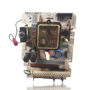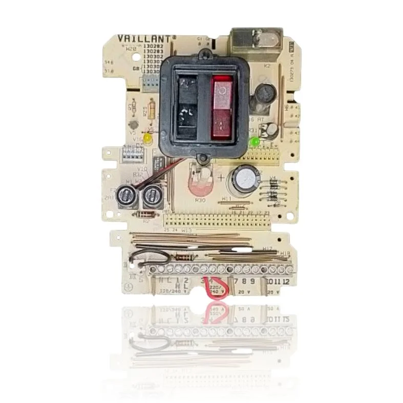
Vaillant PCB VCW Vent 240 01E Ref. 252945
Vaillant electronic PCB/module for the VC/VCW boiler range, including the VCW Vent 240 01E. In the catalog, it is listed with reference 252945, but on the PCB itself, next to the 12-pin connector, the codes 252960 and 252962 are engraved on the hybrid module marked Vaillant.
VAT included
Consult via WhatsAppVaillant boilers compatible with reference 252945
PCB with reference 252945. 14 verified compatibilities: VC 110 T and VC 112 E.
Proven compatibility
| Boiler model | Family | Verification |
|---|---|---|
| Vaillant VC 110 T | Thermocompact (VC) | Contrasted |
| Vaillant VC 112 E | Thermocompact (VC) | Contrasted |
| Vaillant VC 142 E | Thermocompact (VC) | Contrasted |
| Vaillant VC 180 T | Thermocompact (VC) | Contrasted |
| Vaillant VC 182 E | Thermocompact (VC) | Contrasted |
| Vaillant VC 221 T | Thermocompact (VC) | Contrasted |
| Vaillant VC 240 T | Thermocompact (VC) | Contrasted |
| Vaillant VC 242 E | Thermocompact (VC) | Contrasted |
| Vaillant VC 282 E | Thermocompact (VC) | Contrasted |
| Vaillant VCW 221 T | Thermocompact (VC) | Contrasted |
| Vaillant VCW 240 T | Combicompact (VCW) | Contrasted |
| Vaillant VCW 242 E | Combicompact (VCW) | Contrasted |
| Vaillant VCW 280 T | Combicompact (VCW) | Contrasted |
| Vaillant VCW 282 E | Combicompact (VCW) | Contrasted |
Can't see your model or have questions? The printed reference takes precedence. How to check it · Send us a photo via WhatsApp.
How to check if the part number 252945 is the one for your boiler.
What determines it is not the boiler model, but the reference printed on the part you already have installed.
- Find the reference printed on the installed part and check whether it matches the catalogue reference 252945. If it is not visible, do not identify the part from its shape alone.
- Check the full boiler model on its data plate and look for it in the model associations on this page.
- Compare the connections and physical body with the original part before installation.
- If anything is unclear, send us a photo of the marking via WhatsApp before placing your order.
Symptoms and faults that the PCB 252945 resolves.
The PCB controls the ignition, modulation, and safety features of the boiler. These are the typical symptoms and what to do:
Common symptoms and faults
- 01
The boiler does not respond to any controls, neither local nor from the thermostat in the house.
Cause: The electronic module manages all communication of the boiler; if it fails, it stops receiving commands.
Check that the thermostat has batteries and that the wiring or signal is working properly before replacing the module.
- 02
A fault warning appears that turns on and off by itself, without a constant fault.
Cause: The sensor reading circuits of the module are intermittently failing.
Note when the fault occurs (during startup, while running, when stopping) to rule out that it is a specific component.
- 03
The circulation pump never stops, not even when the boiler is in standby.
Cause: A relay on the module that controls the pump gets stuck in the on position.
Cut off the power to the boiler for a moment: if the pump keeps running with the boiler off, the relay is stuck.
- 04
The fuse blows again as soon as it is replaced and the boiler is turned on.
Cause: There is an internal short circuit in the module that suddenly draws more current than the fuse can handle.
Do not insist on replacing the fuse several times in a row: if it blows repeatedly, the fault is internal.
Fault codes from Vaillant that this part resolves.
| Code | Fault | Diagnosis and solution |
|---|---|---|
| F.61 | Gas valve control error. | The output/driver stage of the PCB (252945) does not energise the valve; if coils and wiring are OK, the electronics are the cause. Check for 230 V at the valve during start-up, and if no voltage is present with correct power supply, replace the PCB. |
| F.62 | Gas valve disconnection delay. | If the gas valve and flame signal are correct, the fault is usually in the electronics that de-energise the valve. Check for tightness/ionisation; if everything is correct, check the output/relay-triac on the PCB and replace it if the issue persists. |
| F.63 | EEPROM error (memory) – defective electronics. | The EEPROM of the PCB (252945) is damaged/not readable; the equipment locks up. Check voltages 5 V/24 V and, if wiring/sensors are fine, the documented solution is to replace the PCB. |
| F.64 | Electronic system/NTC fault. | The measurement circuit on the PCB detects a short circuit/implausible value or the electronics are defective. Measure the NTCs and wiring; if they are correct and the fault persists, the cause is the PCB. |
| F.65 | Electronics temperature too high / defective electronics. | The PCB overheats or its internal sensor fails, causing a lockout. Check ventilation/temperature; if it reoccurs without external overheating, replace the PCB. |
| F.70 | Invalid appliance code (DSN). | Coding mismatch between display and PCB or missing/incorrect coding resistor on the PCB (typical after changing the board without parameterization). Verify and reprogram DSN/coding; if it does not recognize the resistor, replace the PCB. |
These symptoms can have more than one cause. If your boiler displays a fault code, send it to us via WhatsApp along with a photo of the labeling, and we'll tell you if this is the part.
Data sheet for the Vaillant 252945 PCB.
- Catalogue reference
- 252945
- Brand
- Vaillant
- Type of part
- PCBs (control boards)
- Units in stock
- 5 units
- Status
- Refurbished
- Warranty
- 1 year
- Shipping
- Delivery time shown at checkout
- Return
- 14 days
Data read on the part and in the manufacturer's documentation
What we have not been able to verify does not appear here.
- Manufacturer of the hybrid module
- Vaillant
- Hybrid module code
- 252960 / 252962
Manuals and technical documentation
Official documentation of the boiler, useful for locating the part and cross-referencing the fault codes.
- Vaillant VCW 280 T manual (PDF)Document © Vaillant, provided as a technical reference.
Frequently asked questions about the PCB 252945
Does the Vaillant PCB Ref. 252945 have the Vaillant logo marked on it?
Does this PCB work for the Combicompact range (VCW)?
Is it an original Vaillant PCB?
How many models are compatible with this PCB?
What fault codes are documented for this PCB?
Where can I find more information about the reference of this PCB?
Spare parts related to Vaillant Thermocompact (VC)