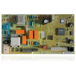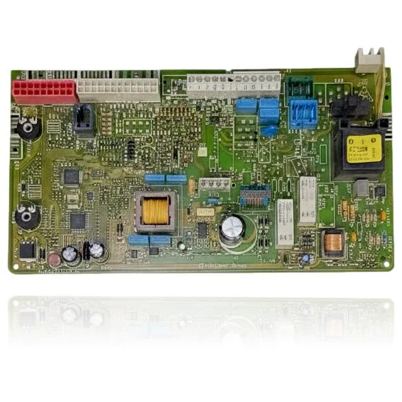
Vaillant PCB VMW 242 4 5 M R1 Turbotec Classic Ref. 0020035443
The Vaillant VMW 242 4 5 M R1 Turbotec Classic PCB (control board) Ref. 0020035443 is the component responsible for controlling the ignition, burner modulation, pump, and safety features of the boiler. When it malfunctions, the boiler may fail to start, become locked, or operate erratically. Users may notice faults such as F.61 related to the gas valve or F.64 indicating problems in the electronics or sensors. This PCB is compatible with models from the VU and VUW ranges, such as the 242/5-5 and 282/3-5, among others. It should be replaced when the mentioned symptoms are detected or when the associated fault codes appear.
VAT included
Consult via WhatsAppVaillant boilers compatible with reference 0020035443
PCB with reference 0020035443. Seven confirmed compatibilities: 202/5-5 and 242/5-5.
Proven compatibility
| Boiler model | Family | Verification |
|---|---|---|
| Vaillant 202/5-5 | VU | Contrasted |
| Vaillant 242/5-5 | VU | Contrasted |
| Vaillant 202/3-3 | VUW | Contrasted |
| Vaillant 242/3-3 | VUW | Contrasted |
| Vaillant 242/5-5 | VUW | Contrasted |
| Vaillant 282/3-5 | VUW | Contrasted |
| Vaillant 322/3-5 | VUW | Contrasted |
Can't see your model or have questions? The printed reference takes precedence. How to check it · Send us a photo via WhatsApp.
How to check if the reference 0020035443 is the part for your boiler
What determines it is not the boiler model, but the reference printed on the part you already have installed.
- Find the reference printed on the installed part and check whether it matches the catalogue reference 0020035443. If it is not visible, do not identify the part from its shape alone.
- Check the full boiler model on its data plate and look for it in the model associations on this page.
- Compare the connections and physical body with the original part before installation.
- If anything is unclear, send us a photo of the marking via WhatsApp before placing your order.
Symptoms and faults that the PCB 0020035443 resolves.
The PCB controls the ignition, modulation, and safety features of the boiler. These are the typical symptoms and what to do:
Common symptoms and faults
- 01
The boiler does not ignite and does not display any fault code; it simply does not respond.
Cause: The microprocessor on the PCB is not starting, so the system that manages the display is down.
Disconnect the boiler from the power supply for 30 seconds and then restore power to force a complete reset before replacing the PCB.
- 02
The equipment works well for a while and then locks up, and only returns after manually resetting.
Cause: An intermittent fault in the PCB, due to soldering or degraded components, causes lockouts that can be reset but keep recurring.
Keep track of how long it takes for the blockage to repeat; a regular pattern points more to the PCB than to an external component.
- 03
The outdoor sensor does not seem to affect the operation, as if the boiler does not take it into account.
Cause: The input from the external sensor is managed by the PCB; if that reading circuit fails, the boiler ignores its values even if the sensor is functioning properly.
Measure the resistance of the outdoor sensor according to the actual ambient temperature and compare it with the table before discarding it.
- 04
Do you notice that the equipment vibrates or makes banging noises during startup, and sometimes that coincides with it stopping responding?
Cause: A cold solder joint on the PCB can lose contact due to the vibration from the fan or the pump when starting up.
Gently tap the casing of the PCB during startup and observe if the fault recurs or disappears; it is a sign of poor internal contact.
Fault codes from Vaillant that this part resolves.
| Code | Fault | Diagnosis and solution |
|---|---|---|
| F.61 | Gas valve activation error. | The valve driver on the PCB does not switch/read the valve correctly, and the equipment locks out for safety. Check voltage/signal from PCB to the valve and harness; if the valve closes/operates well in a direct test, the cause is the PCB. |
| F.62 | Delay in gas valve disconnection. | Valve control stage on the PCB remains 'stuck' or sends a closing command out of time. Check the signal from the PCB to the coils and the valve's tightness/closure; if the valve functions correctly in the test and the fault persists, the PCB is the cause. |
| F.63 | EEPROM fault (defective electronics). | Corruption/damage of the EEPROM in the PCB causes the control not to start or to freeze. Check reprogramming/parameterization if applicable; if not possible or it fails again, replace the PCB ref. 0020035443. |
| F.64 | Fault in the electronics/sensors (NTC) or defective electronics. | The ADC input/measurement stage on the PCB interprets short/incorrect values even though the NTCs are fine. Rule out NTC/wiring with resistance measurement; if they are correct, the PCB is damaged. |
| F.65 | Temperature of the electronics too high. | The PCB detects overheating (internal sensor or damaged electronics). Check the actual temperature in the electronic box/ventilation and external causes; if it is normal and still shows F.65, the PCB is defective. |
| F.67 | Fault: electronics/flame (flame signal not plausible). | The detection stage in the PCB interprets 0/5 V or an unlikely ionisation signal due to electronic fault. Check electrode/wiring/flame guard; if all OK and it persists, the defect is in the PCB. |
| F.70 | Invalid appliance code (DSN)/incorrect parameterization. | After replacing the display and PCB simultaneously or using an incorrect coding resistor, the PCB remains without a valid DSN. Verify/adjust the DSN and coding resistor according to the service manual; if it cannot be parameterized, replace with the correct PCB. |
These symptoms can have more than one cause. If your boiler displays a fault code, send it to us via WhatsApp along with a photo of the labeling, and we'll tell you if this is the part.
Data sheet for the PCB Vaillant 0020035443
- Catalogue reference
- 0020035443
- Brand
- Vaillant
- Type of part
- PCBs (control boards)
- Units in stock
- 4 units
- Status
- Refurbished
- Warranty
- 1 year
- Shipping
- Delivery time shown at checkout
- Return
- 14 days
Data read on the part and in the manufacturer's documentation
What we have not been able to verify does not appear here.
- voltage
- 12V
- frequency
- 50Hz
- material
- PCB
- type/model of the component
- Rev. 1.0
Frequently asked questions about the PCB 0020035443
Is this PCB compatible with my Vaillant VUW 242/3-3?
Spare parts related to Vaillant VUW