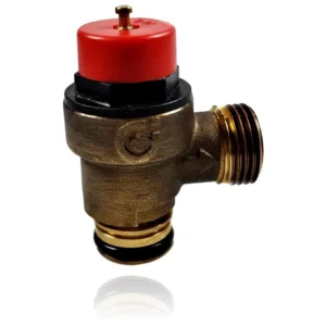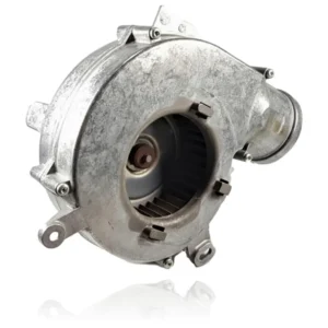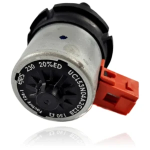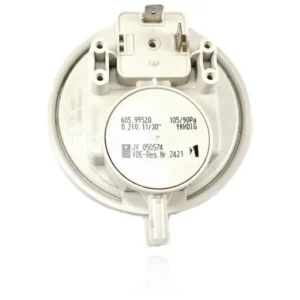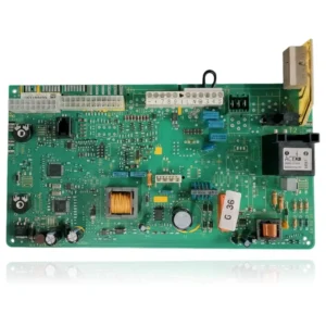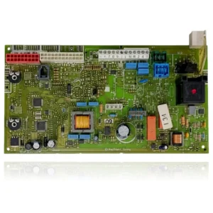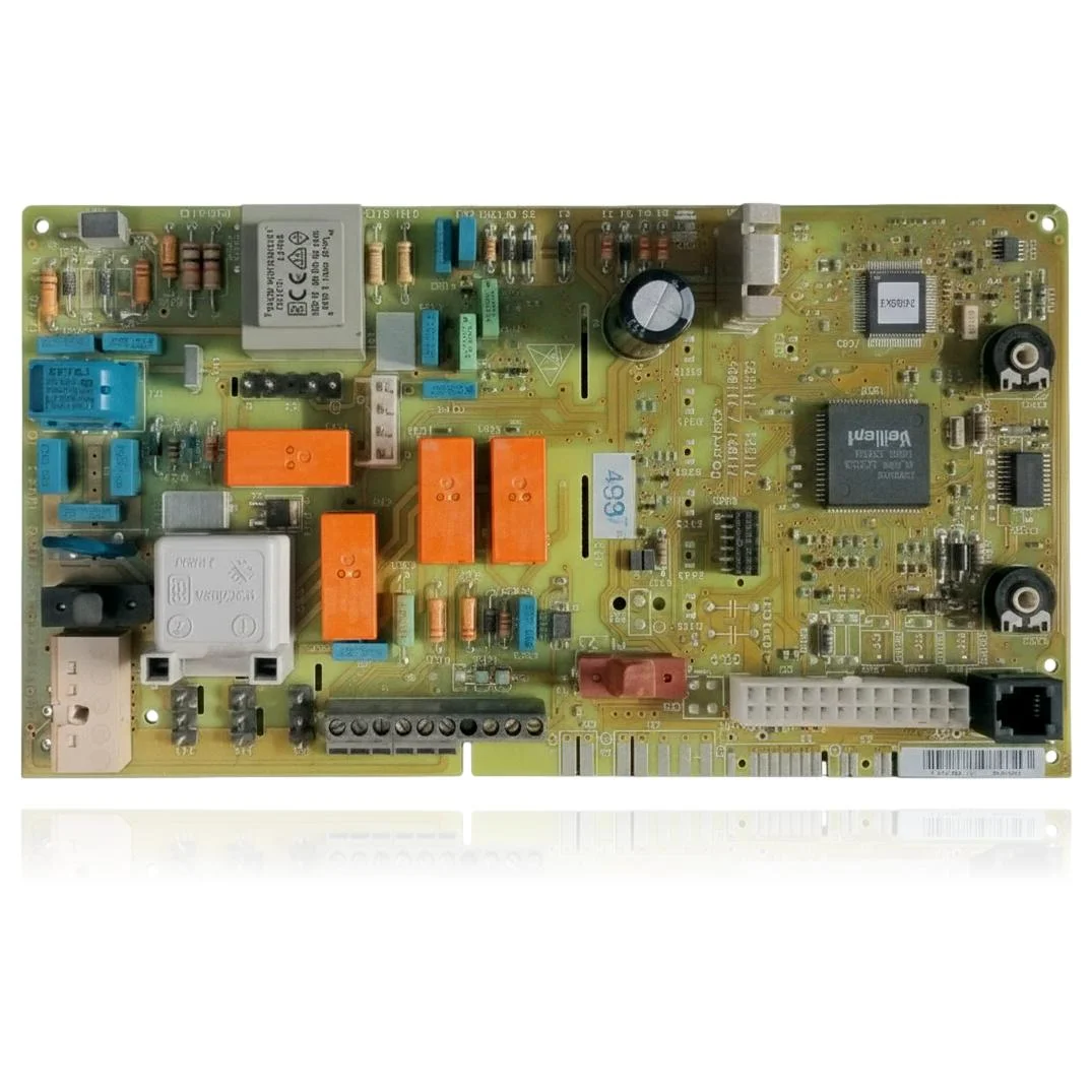
Vaillant PCB Control VMW 242 3 5 M Turbotec Classic Ref. 0020092371
If your boiler does not start, locks out, or exhibits erratic behavior, you may need the Vaillant VMW 242 3 5 M Turbotec Classic Control PCB Ref. 0020092371. This component is responsible for controlling the ignition, burner modulation, pump, and safety features of the boiler. When it fails, you may experience faults such as F.63, F.64, F.65, or F.67. It is compatible with models from the Turbotec Pro, Turbotec Plus, and Atmotec Pro/Plus ranges, among others. It is recommended to replace it when it shows operational failures or errors in the electronics.
Vaillant boilers compatible with reference 0020092371
PCB with reference 0020092371. 11 verified compatibilities: VMW 242/4-3 M R1 and VMW 242/4-3 M.
Proven compatibility
| Boiler model | Family | Verification |
|---|---|---|
| Vaillant VMW 242/4-3 M R1 | Turbotec Pro (VMW) | Contrasted |
| Vaillant VMW 242/4-3 M | Turbotec Pro (VMW) | Contrasted |
| Vaillant VMW 202/4-3 M | Turbotec Pro (VMW) | Contrasted |
| Vaillant VMW 242/4-5 M | Turbotec Plus (VMW) | Contrasted |
| Vaillant VMW 242/4-5 M R2 | Turbotec Plus (VMW) | Contrasted |
| Vaillant VMW 282/4-5 R2 | Turbotec Plus (VMW) | Contrasted |
| Vaillant VMW 322/4-5 R2 | Turbotec Plus (VMW) | Contrasted |
| Vaillant VMW 240/3-3 M | Atmotec Pro/Plus (VMW) | Contrasted |
| Vaillant VMW 240/3-5 M | Atmotec Pro/Plus (VMW) | Contrasted |
| Vaillant VMW 280/3-5 | Atmotec Pro/Plus (VMW) | Contrasted |
| Vaillant VMW 282/4-3 | Atmotec Pro/Plus (VMW) | Contrasted |
Can't see your model or have questions? The printed reference takes precedence. How to check it · Send us a photo via WhatsApp.
How to check if ref. 0020092371 is the part for your boiler
What determines it is not the boiler model, but the reference printed on the part you already have installed.
- Find the reference printed on the installed part and check whether it matches the catalogue reference 0020092371. If it is not visible, do not identify the part by its shape alone.
- Check the full boiler model on its data plate and look for it in the model associations on this page.
- Compare the connections and physical body with the original part before installation.
- If anything is unclear, send us a photo of the marking via WhatsApp before placing your order.
Symptoms and faults that the PCB 0020092371 resolves.
The PCB controls the ignition, modulation, and safety features of the boiler. These are the typical symptoms and what to do:
Common symptoms and faults
- 01
The boiler ignites, makes an attempt, and shuts down after a few seconds, going into lockout.
Cause: The PCB interrupts the start-up if it does not receive the flame or pressure switch signal in time; a fault in that management interrupts the cycle before it stabilizes.
Make sure that the flame remains visible and stable during the attempt before assuming that the fault is in the PCB and not in the burner.
- 02
A temperature sensor fault message appears on the screen, but you have checked the sensor and it is fine.
Cause: The PCB interprets the resistance of the sensor; if its reading circuit fails, it shows an error even if the sensor is within normal values.
Measure the resistance of the sensor when cold and compare it with the manufacturer's table before discarding it and blaming the PCB.
- 03
One of the output relays (pump, fan, or gas valve) is sticking and not shutting off when it should.
Cause: The mechanical relays on the PCB age with use and can become stuck closed, keeping a component active that shouldn't be.
Listen for the click of the relay when starting and stopping the cycle; if the component remains active without that click, it indicates a stuck relay.
- 04
The boiler responds differently depending on whether it has been on for a short or long time, as if it worsens when it heats up.
Cause: A component on the PCB degraded by heat may fail only when the assembly reaches a certain operating temperature.
Note if the fault always appears after the same operating time; this information helps confirm a thermal failure of the PCB.
Fault codes from Vaillant that this part resolves.
| Code | Fault | Diagnosis and solution |
|---|---|---|
| F.63 | EEPROM error: the configuration/calibration memory of the electronics is damaged. | The EEPROM physically resides on this main PCB; when the documentation indicates 'electronic system fault', the cause is the PCB itself. Verify: the code persists after resetting and does not depend on any external component (valve, sensors); if it reappears, replace the PCB. |
| F.64 | Electronic system error / sensors: fault in the electronics or short circuit in the flow or return sensor. | The documented cause explicitly includes 'faulty electronic system' (the PCB). First, check the NTC flow/return sensors (resistance and connections); if the sensors and their wiring are correct and the fault persists, the origin is this board. |
| F.65 | Electronic system temperature too high: the electronics have overheated. | The temperature sensor is integrated into the PCB; the fault code is triggered by external overheating of the PCB or by a fault in the electronics itself. Check: rule out external heat sources or poor ventilation; if the location is correct and the issue persists, the PCB is defective. |
| F.67 | Flame control input signal out of limits (flame detection electronics). | The documented cause is 'electronic system fault': the flame detection/ionisation stage of the PCB delivers a signal out of range. First, check the ionisation electrode and its wiring; if they are correct and the signal remains out of limits, the fault is with this PCB. |
These symptoms can have more than one cause. If your boiler displays a fault code, send it to us via WhatsApp along with a photo of the labeling, and we'll tell you if this is the part.
Data sheet for the PCB Vaillant 0020092371
- Catalogue reference
- 0020092371
- Brand
- Vaillant
- Type of part
- PCBs (control boards)
- Units in stock
- 0 units
- Status
- Refurbished
- Warranty
- 1 year
- Shipping
- Delivery time shown at checkout
- Return
- 14 days
Frequently asked questions about the PCB 0020092371
How do I know if the Vaillant VMW 242 3 5 M Turbotec Classic Control PCB Ref. 0020092371 is compatible with my boiler?
Which Vaillant boiler models are compatible with this PCB?
What fault codes are relevant for this PCB?
Where can I find the reference for this PCB?
What should I do if my boiler shows a fault?
Spare parts related to Vaillant Turbotec Plus (VMW)