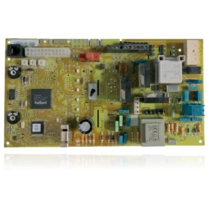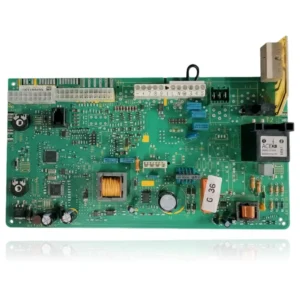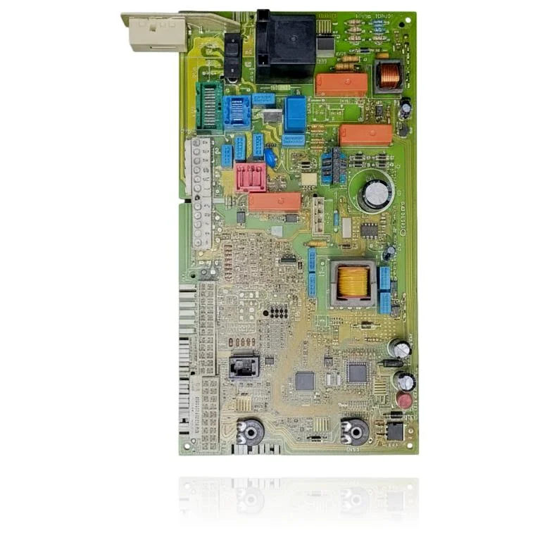
Main Control PCB Vaillant VMW 242 4 Ref. 0020092371
In Vaillant boilers from the Turbotec and Atmotec ranges, the Vaillant VMW 242 4 Main Control PCB Ref. 0020092371 manages essential functions such as ignition, burner modulation, and safety features. When this part fails, the boiler may not start, become locked, or exhibit erratic behavior. Additionally, it may display faults such as F.63, F.64, F.65, or F.67. It is compatible with models such as VMW 242/4-3 M R1, VMW 242/4-5 M, among others. It is recommended to replace it upon noticing any of these symptoms or faults.
VAT included
Consult via WhatsAppVaillant boilers compatible with reference 0020092371
PCB with reference 0020092371. 11 verified compatibilities: VMW 242/4-3 M R1 and VMW 242/4-3 M.
Proven compatibility
| Boiler model | Family | Verification |
|---|---|---|
| Vaillant VMW 242/4-3 M R1 | Turbotec Pro (VMW) | Contrasted |
| Vaillant VMW 242/4-3 M | Turbotec Pro (VMW) | Contrasted |
| Vaillant VMW 202/4-3 M | Turbotec Pro (VMW) | Contrasted |
| Vaillant VMW 242/4-5 M | Turbotec Plus (VMW) | Contrasted |
| Vaillant VMW 242/4-5 M R2 | Turbotec Plus (VMW) | Contrasted |
| Vaillant VMW 282/4-5 R2 | Turbotec Plus (VMW) | Contrasted |
| Vaillant VMW 322/4-5 R2 | Turbotec Plus (VMW) | Contrasted |
| Vaillant VMW 240/3-3 M | Atmotec Pro/Plus (VMW) | Contrasted |
| Vaillant VMW 240/3-5 M | Atmotec Pro/Plus (VMW) | Contrasted |
| Vaillant VMW 280/3-5 | Atmotec Pro/Plus (VMW) | Contrasted |
| Vaillant VMW 282/4-3 | Atmotec Pro/Plus (VMW) | Contrasted |
Can't see your model or have questions? The printed reference takes precedence. How to check it · Send us a photo via WhatsApp.
How to check if ref. 0020092371 is the part for your boiler
What determines it is not the boiler model, but the reference printed on the part you already have installed.
- Find the reference printed on the installed part and check whether it matches the catalogue reference 0020092371. If it is not visible, do not identify the part by its shape alone.
- Check the full boiler model on its data plate and look for it in the model associations on this page.
- Compare the connections and physical body with the original part before installation.
- If anything is unclear, send us a photo of the marking via WhatsApp before placing your order.
Symptoms and faults that the PCB 0020092371 resolves.
The PCB controls the ignition, modulation, and safety features of the boiler. These are the typical symptoms and what to do:
Common symptoms and faults
- 01
A fixed fault code appears on the display and the reset does not remove it.
Cause: The PCB detects a fault and locks the boiler until it is resolved; if the fault code persists after resetting, the lock is generated by the control electronics.
Note the exact code and compare it with the manual: some codes point to external sensors (NTC, pressure switch) that should be ruled out before replacing the PCB.
- 02
The boiler starts up properly but turns off by itself after a few minutes, repeatedly.
Cause: An internal fault in the electronics can interrupt the combustion sequence even if the flame has formed correctly.
Check that it is not an issue with flue or gas pressure before attributing it to the PCB, as these can also cause similar interruptions.
- 03
There is no light or indication on the panel, the boiler seems dead.
Cause: If the power supply of the PCB fails, no electronic component receives power and there is no visible response.
Confirm that there is mains voltage at the input of the PCB before discarding it; a blown fuse on the board itself can also cause this symptom.
- 04
The thermostat or the remote control is unable to start the boiler.
Cause: The PCB is the one that receives and processes that demand; if the input circuit fails, the ignition command never gets executed.
Check that the remote control has a good connection and batteries, and that the connection terminals to the PCB are not loose, before replacing the component.
Fault codes from Vaillant that this part resolves.
| Code | Fault | Diagnosis and solution |
|---|---|---|
| F.63 | EEPROM error: the configuration/calibration memory of the electronics is damaged. | The EEPROM physically resides on this main PCB; when the documentation indicates 'electronic system fault', the cause is the PCB itself. Verify: the code persists after resetting and does not depend on any external component (valve, sensors); if it reappears, replace the PCB. |
| F.64 | Electronic system error / sensors: fault in the electronics or short circuit in the flow or return sensor. | The documented cause explicitly includes 'faulty electronic system' (the PCB). First, check the NTC flow/return sensors (resistance and connections); if the sensors and their wiring are correct and the fault persists, the origin is this board. |
| F.65 | Electronic system temperature too high: the electronics have overheated. | The temperature sensor is integrated into the PCB; the fault code is triggered by external overheating of the PCB or by a fault in the electronics itself. Check: rule out external heat sources or poor ventilation; if the location is correct and the issue persists, the PCB is defective. |
| F.67 | Flame control input signal out of limits (flame detection electronics). | The documented cause is 'electronic system fault': the flame detection/ionisation stage of the PCB delivers a signal out of range. First, check the ionisation electrode and its wiring; if they are correct and the signal remains out of limits, the fault is with this PCB. |
These symptoms can have more than one cause. If your boiler displays a fault code, send it to us via WhatsApp along with a photo of the labeling, and we'll tell you if this is the part.
Data sheet for the PCB Vaillant 0020092371
- Catalogue reference
- 0020092371
- Brand
- Vaillant
- Type of part
- PCBs (control boards)
- Units in stock
- 2 units
- Status
- Refurbished
- Warranty
- 1 year
- Shipping
- Delivery time shown at checkout
- Return
- 14 days
Spare parts related to Vaillant Turbotec Plus (VMW)