

Vaillant PCB VMW ES 242 2 3 - Code 734739
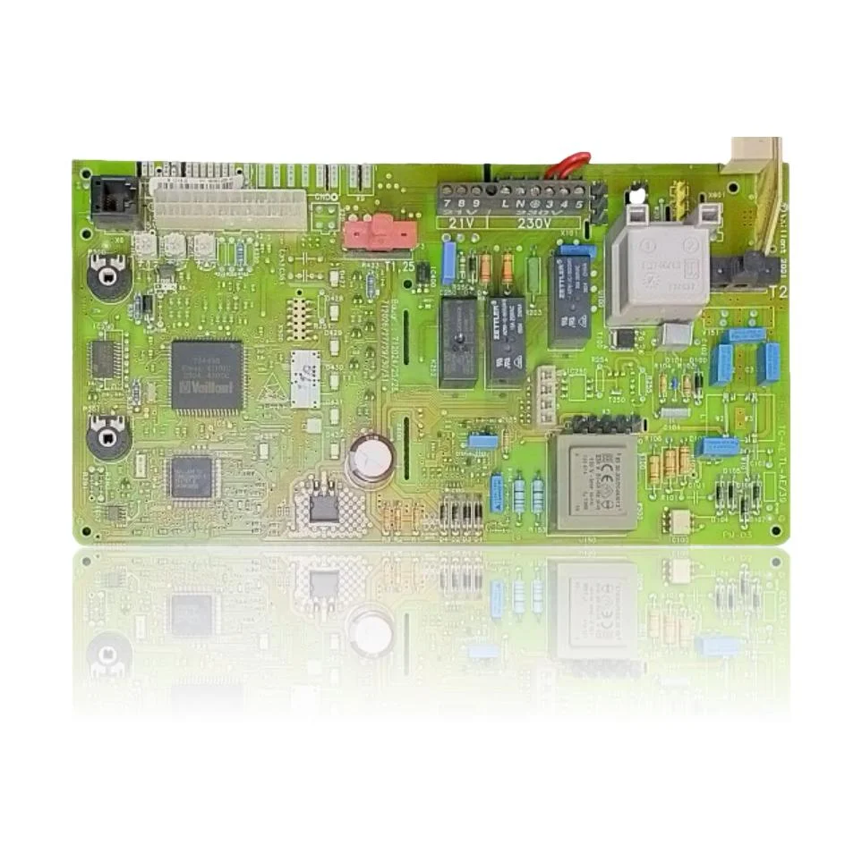
When you turn on the tap or the heating, the Vaillant VMW ES 242 2 3 PCB, reference 734739, is responsible for controlling the ignition, the modulation of the burner, and the boiler pump. If this part fails, you will notice that the boiler does not start, gets locked, or exhibits erratic behavior. It is compatible with models such as the VMW ES 242/2-3 and VMW ES 242/2-5, among others. A technician must confirm through diagnosis whether it needs to be replaced when errors such as F.61, F.62, F.63, F.64, or F.65 appear, or if the boiler shows operational faults.
- Type of part
- PCBs (control boards)
- Status
- Refurbished
- Catalogue reference
- 00712025
- Warranty
- 1 year
Vaillant boilers compatible with reference 00712025
PCB with reference 00712025. Two confirmed compatibilities: VMW ES 242/2-3 and VMW ES 242/2-5.
Proven compatibility
| Boiler model | Family | Verification |
|---|---|---|
| Vaillant VMW ES 242/2-3 | Turbotec (VMW ES 242 / Turbotec Classic) | Contrasted |
| Vaillant VMW ES 242/2-5 | Turbotec (VMW ES 242 / Turbotec Classic) | Contrasted |
Can't see your model or have questions? The printed reference takes precedence. How to check it · Send us a photo via WhatsApp.
How to check if ref. 00712025 is the part for your boiler
The part reference, model, and equipment revision must be verified against the manufacturer's documentation.
- Find the reference printed on the installed part and check whether it matches the catalogue reference 00712025. If it is not visible, do not identify the part from its shape alone.
- Check the full boiler model on its data plate and look for it in the model associations on this page.
- Compare the connections and physical body with the original part before installation.
- If anything is unclear, send us a photo of the marking via WhatsApp before placing your order.
Symptoms that require diagnosis on the PCB 00712025
The PCB controls the ignition, modulation, and safety features of the boiler. These are the typical symptoms and what to do:
Common symptoms and faults
- 01
The boiler is completely dead: it doesn't light up even a single indicator, it doesn't respond to anything.
Cause: A blown fuse or a fault in the transformer of the PCB cuts off power to the entire control circuit.
Measure with a multimeter if the T2 250mA fuse has continuity before declaring the PCB dead and replacing it entirely.
- 02
It turns on, goes through the cycle, and stops showing a different fault code each time you try.
Cause: When the relays on the PCB fail, erratic readings reach the control unit and a different lockout occurs with each attempt.
Note the fault codes that appear during various starts; if they do not consistently point to the same component (flame, NTC, pressure switch), the suspicion falls on the PCB.
- 03
The thermostat in the house is unable to start the boiler, although the programmer is working fine.
Cause: The PCB receives the ignition command but does not transmit it to the power stage, or the connector with the thermostat is damaged.
Check that the thermostat cable or bus is properly connected to the PCB and free of oxidation before replacing it.
- 04
A click is heard from the relay when requesting heat, but the boiler does not start the ignition cycle.
Cause: The relay closes the contact but there is not enough current reaching the next stage: fan, gas valve, or electrode.
Measure if the fan or the gas valve receive voltage right at the moment of that click; if nothing arrives, the PCB is the main suspect.
- 05
The fault comes and goes: some days the boiler ignites without any problem and other days it remains dead without you having touched anything.
Cause: A cold solder joint or a microfracture on the PCB tracks causes intermittent faults that appear with temperature or vibrations.
Gently tap the control board while it is failing; if the problem appears or disappears with the tap, it points to a cold solder joint on the PCB.
Vaillant fault codes that require diagnosis
| Code | Fault | Technical checks |
|---|---|---|
| F.61 | Gas valve activation error | The output stage of the PCB does not correctly excite the coils of the gas valve (driver/output faulty), causing the fault. Check the continuity of the harness and the control signal to the valve during demand; if the valve and wiring are correct and there is no signal (or it drops unexpectedly), the PCB is the cause. |
| F.62 | Gas valve disconnection delay | The circuit of the PCB maintains the power supply to the gas valve longer than it should or does not cut off in time (stuck driver), registering delayed disconnection. Check that the signal to the coils drops to 0 when turned off and that the ionisation extinguishes; if everything is correct and the delay persists, the PCB is defective. |
| F.63 | Error: EEPROM | Corruption/invalid reading of the EEPROM memory of the PCB or its associated electronics. Confirm after reset/brief power cut that the error reappears; if network/grounding are fine, the documented solution is to replace or reprogram the PCB. |
| F.64 | Fault: PCB / sensor (NTC) | Fault in the conditioning/ADC on the board that measures the NTCs (incoherent readings). Check NTC for resistance and wiring; if values are correct but the boiler still shows F.64, the defect is in the PCB. |
| F.65 | Error: electronics temperature too high | Actual overheating or erroneous temperature sensor reading on the PCB. Check ventilation/temperature of the compartment and heat sinks; if there are no external causes and the error persists, the PCB is damaged. |
| F.67 | Incorrect value returned by ASIC (flame signal) | Anomaly in the flame detection circuit of the PCB (signal not plausible). Check ionisation electrode, ground, and cable; if they are correct and F.67 persists, the flame electronics of the PCB is faulty. |
| F.70 | Invalid product code (DSN) | After replacing the display and/or board, the new PCB is not coded with the appliance variant, causing DSN incompatibility. Verify the model coding and reprogram the board; if it does not accept coding or loses it, the PCB is the cause. |
These symptoms can have more than one cause. If your boiler displays a fault code, send it to us via WhatsApp along with a photo of the labeling, and we'll tell you if this is the part.
Data sheet for the Vaillant PCB 00712025
- Catalogue reference
- 00712025
- Uniclima internal SKU
- PLCVMW242
- Brand
- Vaillant
- Type of part
- PCBs (control boards)
- Units in stock
- 6 units
- Status
- Refurbished
- Warranty
- 1 year
- Shipping
- Delivery time shown at checkout
- Return
- 14 days
Part data and available documentation
Contrast the label codes, PCB, and revision with the installed part; they are not necessarily equivalent references.
- Manufacturer
- Vaillant
- Silkscreened code on PCB
- 734739
- Primary transformer voltage
- 230V~ 50-60Hz
- Secondary transformer voltage
- 150V~ / 60mA
- Fuse
- T2 250mA
- Voltage at terminals 7, 8, 9 (low voltage)
- 21V
- Voltage at terminals L, N, 3, 4, 5 (network)
- 230V
- Relay
- Zettler (brand printed on the relays; component manufacturer, not the PCB manufacturer)
Frequently asked questions about the PCB 00712025
Is this PCB compatible with my Vaillant VMW ES 242 2 3?
What fuse does the PCB of the Vaillant VMW ES 242 2 3 use?
What brand of relays does this PCB from the VMW ES 242 2 3 have?
When should this PCB be replaced in a Vaillant VMW ES 242 2 3?