






























































Short answer
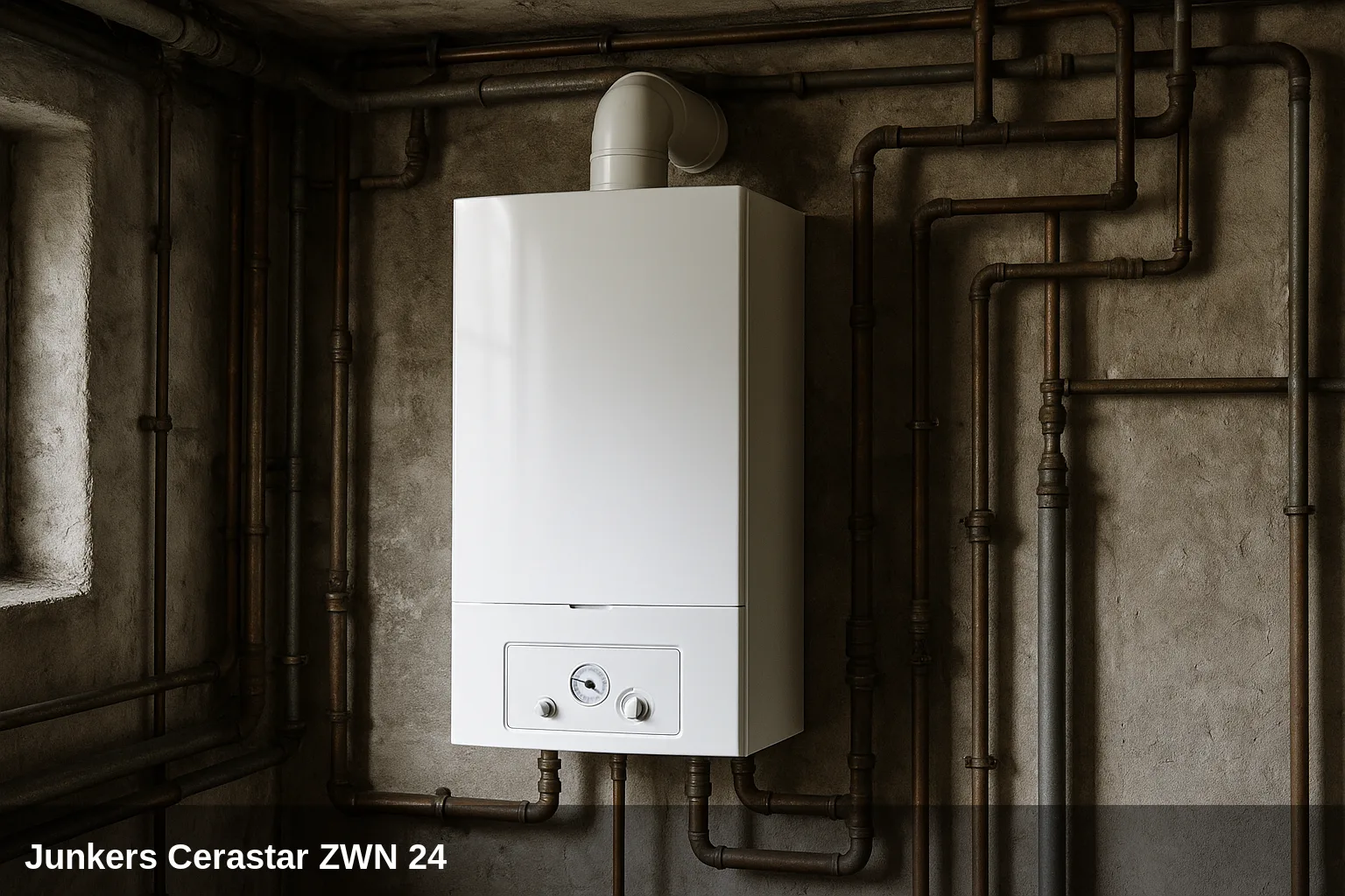
The Junkers Cerastar (ZWN/ZSN/ZWR 24) alerts you of its faults with codes on the display (for example EA, E9 or F7) thanks to its Heatronic system. In this guide, you have the meaning of each code, why it appears, and how to solve it, as well as the exact spare part when the fault corresponds to a specific component. These codes are common to a large part of the Junkers/Bosch range with Heatronic.
Error code table for the Cerastar ZWN 24
Quick summary of all fault codes. Below you have the details of each one with its cause and solution.
| Code | Meaning |
|---|---|
| EA | Flame not detected |
| E9 | Thermal block or flue gas temperature limiter activated |
| F0 | Internal electronics fault |
| F7 | Flame detected with the appliance off or before ignition |
| FA | Flame detected after gas shut-off |
| A1 | The heating pump has run dry. |
| A7 | Defective domestic hot water temperature sensor |
| A8 | Communication interrupted with external accessory (BUS) |
| b1 | Coded connector not detected or incorrect |
| b2 | Internal data error in the PCB |
| b3 | Internal data error in the PCB |
| C6 | The fan is not working or is spinning at the incorrect speed. |
| C7 | Fan faulty or no rotation signal |
| E2 | Defective flow temperature sensor |
| CC | Outdoor temperature sensor not detected |
| D3 | External controller active without detected enabling bridge |
| D5 | Defective external flow temperature sensor (hydraulic) |
| F1 | Internal data error in the PCB or gas valve |
| A4 | Fault in the flue pressure switch or flue gas evacuation system |
| 9U | Defective PCB or encoder |
| Fd | The reset button was pressed accidentally or there was a power cut during operation. |
| H13 | Scheduled maintenance interval reached notification |
What can you check yourself?
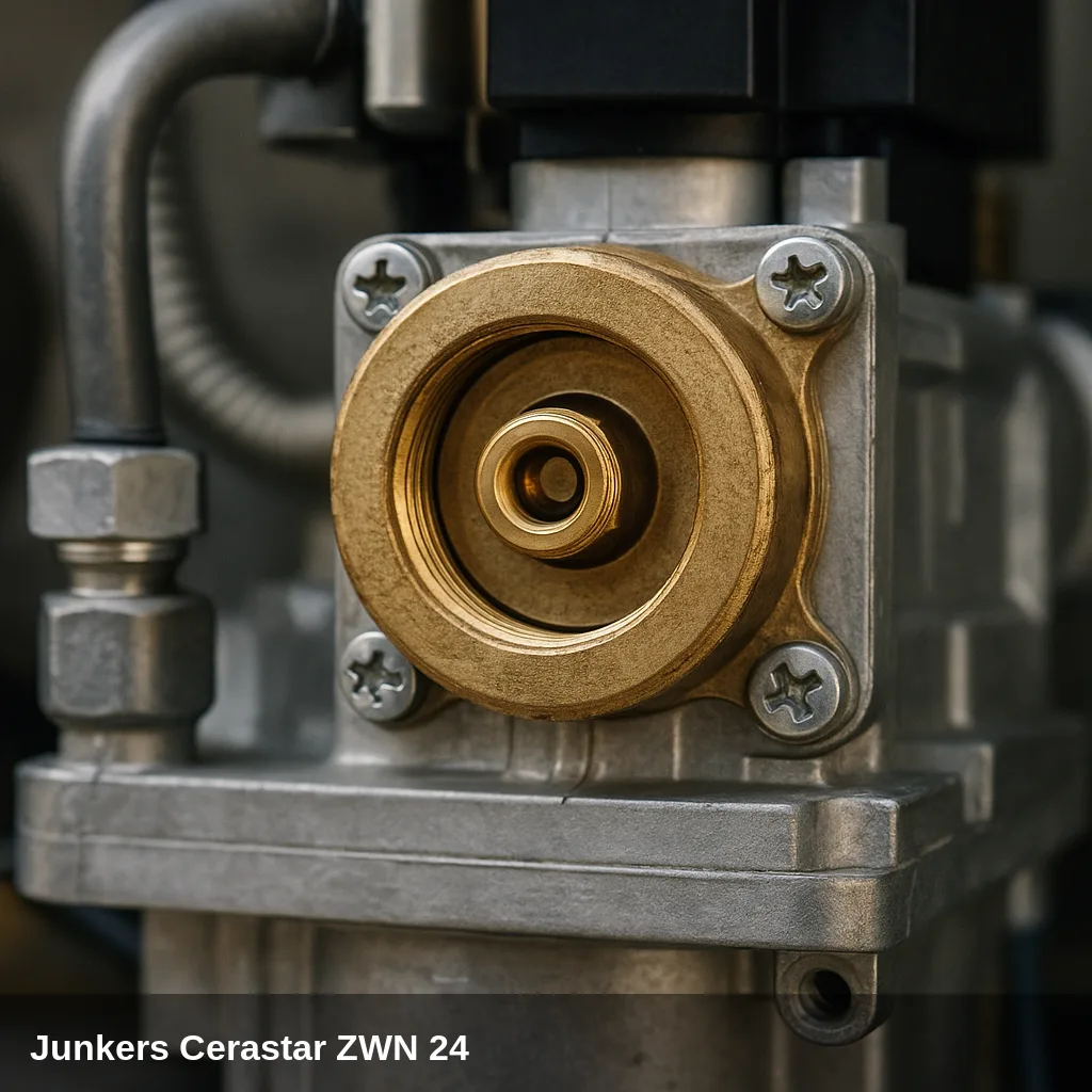
Some alerts can be resolved with simple and safe checks: replenishing the water pressure, bleeding the air from the radiators, checking that the gas valve is open, or resetting the boiler after a temporary lockout. If the code reappears after doing this, there is an underlying cause that should be reviewed by a qualified technician. Do not manipulate internal gas components nor electronics.
How to replenish the pressure step by step
- Locate the filling valve under the boiler.
- Open it slowly while observing the pressure gauge.
- Close the valve upon arrival at between 1 and 1.5 bar in cold.
- Bleed the radiators starting with the furthest one and check the pressure again.
- Reset the boiler; if the pressure warning disappears, the problem was resolved.
All fault codes and their solution
EA — Flame not detected
Why does it appear: The boiler makes several ignition attempts without detecting ionisation at the electrode. Common causes: closed gas valve or insufficient gas pressure, dirty or misaligned ignition electrode, deteriorated electrode cable, defective gas valve, incorrect gas/air ratio, obstructed flue.
What to do: Check that the gas valve is open and that there is a gas supply to other appliances. Verify the pressure of the hydraulic circuit (it should be between 1 and 1.5 bar). Press the reset button for a first attempt at restarting. If the fault persists, a qualified technician needs to inspect the electrode, wiring, and gas valve.
Affected component: Ignition/Ionisation Electrode
E9 — Thermal block or flue gas temperature limiter activated
Why does it appear: The boiler exceeds 105 °C and the safety limiter locks it. Most common causes: low water pressure in the circuit, circulation pump blocked or faulty, air in the hydraulic circuit, lime scale in the heat exchanger, obstruction on the water side of the thermal block.
What to do: Allow the boiler to cool down. Check the pressure on the gauge: if it is below 1 bar, refill the circuit to 1.2-1.5 bar using the filling key. Press the reset button. If the error reappears, a qualified technician needs to check the pump, bleed the circuit, and inspect the heat exchanger.
Browse catalogue: Catalogue: heat exchangers · Junkers
F0 — Internal electronics fault
Why does it appear: Internal error detected by the Heatronic 3 PCB. It may be due to an electrical fault in the power supply, faulty contacts, or a defective PCB.
What to do: Check that the power supply to the boiler is correct and stable. Verify electrical connections and ignition cables. If the fault persists after the reset, the intervention of a qualified technician is necessary for diagnosis and possible replacement of the PCB.
Browse catalogue: Catalogue: circuit boards · Junkers
F7 — Flame detected with the appliance off or before ignition
Why does it appear: The electronics detect an ionization signal when the boiler is not in the ignition process. Causes: dirty or damaged ionization electrode generating a parasitic signal, PCB with a fault in the flame detection circuit, gas valve with defective closure.
What to do: Press the reset button for a first restart attempt. If the error reappears, a qualified technician needs to inspect the ionisation electrode, wiring, and gas valve. Do not operate the boiler if a gas leak is suspected.
Affected component: Ignition/Ionisation Electrode
FA — Flame detected after gas shut-off
Why does it appear: The electronics continue to detect ionisation after the gas valve should have closed. This indicates poor closure of the gas valve or a fault in the flame detection circuit.
What to do: Requires immediate intervention by a qualified technician for inspection and replacement of the gas valve. It may also be advisable to check the condensate trap and the flue. Do not attempt to repair on your own.
Affected component: Gas valve
A1 — The heating pump has run dry
Why does it appear: The circulation pump has operated without sufficient water in the circuit. Common cause: hydraulic circuit pressure too low (below 0.5 bar), water loss in the circuit, or trapped air.
What to do: Check the pressure on the pressure gauge. If it is below 1 bar, fill the circuit up to 1.2-1.5 bar and bleed the air. Press the reset button. If the error frequently reappears, a qualified technician should check for possible leaks and the condition of the pump.
Affected component: Circulation pump
A7 — Faulty domestic hot water temperature sensor
Why does it appear: The NTC sensor of the domestic hot water (DHW) circuit shows an open circuit, short circuit, or out-of-range reading. This may be due to a sensor damaged by scale or an electrical fault in the connection cable.
What to do: Requires intervention by a qualified technician to check the electrical continuity of the sensor and the connection cable, and replace the NTC sensor if it is found to be defective.
Affected component: Temperature sensor
A8 — Communication interrupted with external accessory (BUS)
Why does it appear: Communication between the boiler and an accessory connected via BUS (such as a programmer or external zone module) has been interrupted. Common cause: damaged interconnection cable or loose connection.
What to do: Check the status and connection of the BUS link cable between the boiler and the external accessory. If the cable is correct and the error persists, a qualified technician should diagnose the accessory or the PCB.
Affected component: Electrical installation
b1 — Coded connector not detected or incorrect
Why does it appear: The Heatronic 3 electronics do not recognize the encoded connector (encoder) that identifies the boiler model. This may be due to a disconnected, damaged, or incorrect connector for the model.
What to do: Requires intervention by a qualified technician to verify the connection of the coded connector, check its reference, and replace it if it does not correspond to the model or is defective. In some cases, it is necessary to restore factory settings (function 8E of the service module).
Browse catalogue: Catalogue: circuit boards · Junkers
b2 — Internal data error in the PCB
Why does it appear: Internal fault in the memory or processor of the Heatronic 3 PCB. It is not related to hydraulic operation or gas.
What to do: Requires intervention by a qualified technician. Generally needs diagnosis and possible replacement of the PCB.
Browse catalogue: Catalogue: circuit boards · Junkers
b3 — Internal data error in the PCB
Why does it appear: Internal fault in the memory or processor of the Heatronic 3 PCB. Similar to fault code b2.
What to do: Requires intervention by a qualified technician. Generally needs diagnosis and possible replacement of the PCB.
Browse catalogue: Catalogue: circuit boards · Junkers
C6 — The fan does not work or rotates at incorrect speed
Why does it appear: The flue pressure switch or the electronics detect that the fan does not start, rotates too slowly, or too quickly. Causes: worn fan bearings, loose electrical connection, fan blocked by dirt, or motor fault.
What to do: Press the reset button for a first attempt. If the error persists, a qualified technician should inspect the electrical connections of the fan, clean the impeller, and if the motor is faulty, replace the fan assembly.
Related spare part: Junkers flue fan catalogue
C7 — Fan fault or no rotation signal
Why does it appear: The fan does not start at all or no movement signal is detected. More serious fault than C6. It may be due to a faulty fan motor or a fault in the control circuit.
What to do: Requires intervention by a qualified technician for diagnosis of the fan motor and replacement if necessary. The appliance must not operate without proper ventilation due to the risk of gas accumulation.
Related spare part: Junkers flue fan catalogue
E2 — Faulty flow temperature sensor
Why does it appear: The NTC sensor measuring the water temperature in the heating circuit flow shows an open circuit, short circuit, or out-of-range reading. This may be due to a deteriorated sensor or damaged connection cable.
What to do: Requires intervention by a qualified technician to check the resistance of the NTC sensor with a multimeter (the values must correspond to the manufacturer's temperature table), verify the connection cable, and replace the sensor if it is defective.
Affected component: Temperature sensor
CC — External temperature sensor not detected
Why does it appear: The outdoor temperature sensor is connected to the system but no signal is detected. This could be due to a disconnected sensor, interrupted cable, or faulty sensor.
What to do: Check the continuity of the external sensor cable and its correct connection. If the cable is in good condition, a qualified technician should verify the sensor and replace it if necessary. If an external sensor is not used, this function can be deactivated in the parameter menu.
Affected component: Temperature sensor
D3 — Active external controller detected without enabling bridge
Why does it appear: The electronics detect that there should be an external controller or enabling bridge (bridges 8/9 or PR/PO depending on voltage) but it is not found. This occurs when an external controller has been configured and the bridge or accessory is not properly installed.
What to do: Check the installation of the enable bridge or the external controller. A qualified technician should verify the wiring and the configuration of the corresponding parameter in the technician's menu.
Affected component: Electrical installation
D5 — Faulty external flow temperature sensor (hydraulic)
Why does it appear: The external temperature NTC sensor of the hydraulic flow (buffer tank or manifold) presents a fault. It can be detected as a BUS user or as an analogue sensor depending on the configuration.
What to do: Requires intervention by a qualified technician to check the continuity of the sensor and cable, and replace it if defective. In some cases, it may be necessary to restore the factory settings of the Heatronic 3.
Affected component: Temperature sensor
F1 — Internal data error in the PCB or gas valve
Why does it appear: Internal fault in the Heatronic 3 electronics, sometimes related to the gas valve or its control circuits. Cut-off code requiring technical diagnosis.
What to do: Requires intervention by a qualified technician for diagnosis via the information menu and possible replacement of the PCB or the gas valve.
Browse catalogue: Catalogue: circuit boards · Junkers
A4 — Fault in the flue pressure switch or gas evacuation system
Why does it appear: The pressure switch or forced draught detector indicates a fault in the flue gas evacuation. Common causes: obstructed flue duct, faulty flue gas pressure switch, or fan with insufficient pressure.
What to do: Visually check that the flue duct is not obstructed. A qualified technician should verify the flue pressure switch, the fan flow rate, and the condition of the flue duct.
Related spare part: Junkers flue fan catalogue
9U — Defective PCB or encoder
Why does it appear: The Heatronic 3 PCB or the model encoder presents a fault that prevents the correct operation of the boiler.
What to do: Requires intervention by a qualified technician for diagnosis and replacement of the PCB or the encoder.
Browse catalogue: Catalogue: circuit boards · Junkers
Fd — The reset button was pressed accidentally or there was a power cut during operation
Why does it appear: The Fd code indicates that the appliance has detected an interruption in operation, usually due to an involuntary pressing of the reset button or a power supply cut.
What to do: Press the reset button again for the boiler to resume normal operation. If the code appears without an apparent cause, check the stability of the power supply.
H13 — Scheduled maintenance interval warning reached
Why does it appear: The boiler has a scheduled periodic inspection interval, and the programmed period has expired. It is not a fault and does not block the operation of the boiler.
What to do: Contact a qualified technician to carry out the mandatory periodic inspection (required according to R.I.T.E.). Once the inspection is completed, the technician can reset the interval from menu 2.5F (values 1-72 months; value 0 deactivates the function).
When to call a technician
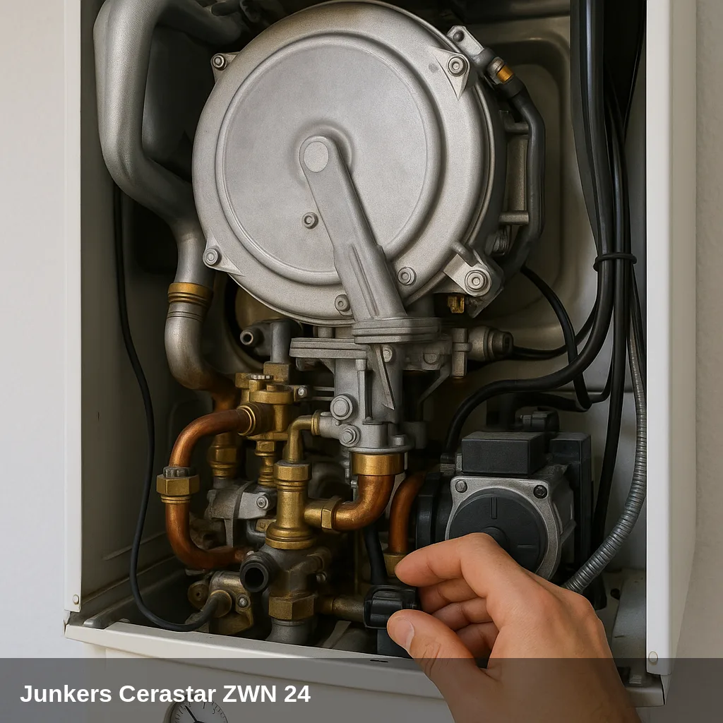
Fault codes related to sensors, electronics, gas valve, fan, or flue gas evacuation require a qualified technician with the appropriate equipment. If the same fault code reappears after a reset, or if the pressure drops repeatedly, a professional inspection is advisable. In Uniclima do you find spare parts for this boiler.
Frequently Asked Questions
EA indicates that there is no ionisation current: the boiler does not detect a flame. This is usually due to a lack of gas, a dirty or poorly positioned ignition/ionisation electrode, or a defective gas valve. Check the gas and reset; if it repeats, a technician should inspect it.
E9 indicates that the safety thermostat (STB) has been triggered due to overheating. It is usually related to the flow NTC sensor, the pump, or the fuses on the PCB. The inspection should be carried out by a technician.
With the reset button on the panel. If the code reappears after resetting, do not insist repeatedly: it indicates an underlying fault that should be diagnosed by a qualified technician.