






























































Short answer
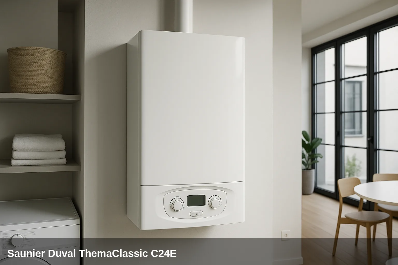
The boiler Saunier Duval ThemaClassic F25 notifies of its faults with fault codes type F.XX on the display. Here you have the complete list: what does each code mean, why does it appear and how to solve it, as well as what you can check yourself and when it is advisable to call a technician.
Fault code table for the ThemaClassic F25
Quick summary of all fault codes. Below you have the details of each one with its cause and solution.
| Code | Meaning |
|---|---|
| F.01 | Ignition fault (no flame after 3 attempts) |
| F.02 | Safety due to lack of draft or flue pressure switch fault |
| F.03 | Repetitive draft fault (F.02 three times) |
| F.04 | Repetitive ignition fault (F.01 three times) |
| F.05 | Overheating: temperature above 90 °C |
| F.06 | Fault in the heating flow NTC sensor |
| F.07 | Domestic hot water NTC sensor fault |
| F.08 | NTC sensor fault of the storage tank |
| F.09 | Water pressure sensor fault |
| F.10 | Short circuit or fault in the return NTC sensor |
| F.11 | Short circuit in return NTC sensor or no signal from the main circuit |
| F.12 | Short circuit in the accumulator sensor or no signal from the interface |
| F.13 | Main PCB fault |
| F.14 | Heating temperature above 95 °C |
| F.15 | Stepper motor fault of the gas valve |
| F.16 | Flame detection fault |
| F.17 | Mains voltage below 170 V |
| F.18 | User interface fault (control panel) |
| F.19 | Loose or faulty heating NTC sensor |
| F.20 | Safety shutdown by temperature limiter |
| F.21 | Insufficient water pressure (below 0.5 bar) |
| F.22 | Excessive water pressure (above 2.7 bar) |
| F.23 | Excessive temperature variation (possible circulation fault) |
| F.24 | Temperature increase too rapid (pump possibly blocked) |
| F.25 | Flue hood temperature sensor fault |
| F.26 | Maximum temperature difference between flow and return or gas valve fault |
| F.27 | Heating flow sensor fault or incorrect flame detection |
| F.28 | Start-up fault: ignition failed at start-up |
| F.29 | Failed ignition during operation |
| F.32 | Fan fault |
| F.42 | Coding resistance fault |
| F.49 | eBUS communication fault |
| F.52 | Flow sensor connection fault |
| F.53 | Flow sensor fault |
| F.54 | Gas pressure fault |
| F.56 | Flow sensor regulation fault |
| F.57 | Operating fault in comfort mode |
| F.61 | Gas valve activation fault |
| F.62 | Gas valve fault: delay in flame shut-off |
| F.63 | EEPROM fault (PCB memory) |
| F.64 | Electronic fault or short circuit in NTC sensor |
| F.65 | Excessive temperature in the electronics |
| F.67 | Flame signal not plausible in the electronics |
| F.68 | Unstable flame signal |
| F.70 | Invalid product code (DSN) |
| F.71 | Heating flow sensor fault |
| F.72 | Excessive temperature difference between flow and return |
| F.73 | Pressure sensor signal too low |
| F.74 | Pressure sensor signal out of range |
| F.77 | Fault in the flue gas flap or in the condensate pump |
| F.79 | Accumulator temperature sensor fault |
| F.81 | Overheating in the domestic hot water (DHW) circuit |
| F.83 | Temperature variation fault in the sensors |
| F.84 | Inconsistent temperature difference between sensors |
| F.85 | Incorrect installation of the flow and return sensors |
| F.86 | Operation of the underfloor heating safety thermostat |
What can you check yourself?
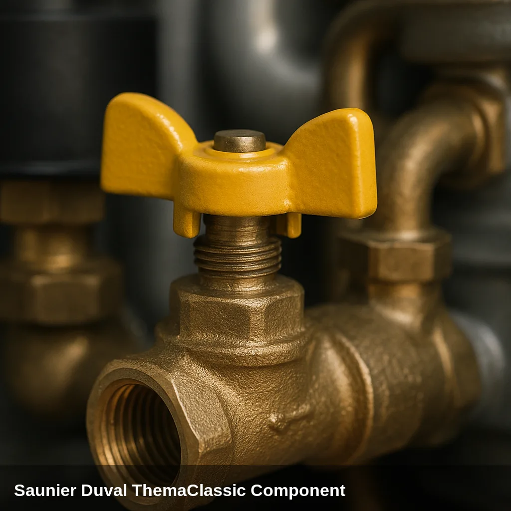
Some warnings can be resolved with simple and safe checks: replenishing the water pressure, bleeding the air from the radiators, checking that the gas valve is open, or resetting the boiler after a temporary lockout. If the code reappears after doing this, there is an underlying cause that should be checked by an authorised technician. Do not manipulate internal gas components nor electronics.
How to replenish the pressure step by step
- Locate the filling valve under the boiler (usually blue in colour).
- Open it slowly while observing the pressure gauge.
- Close the valve upon reaching between 1 and 1.5 bar in cold.
- Bleed the radiators starting with the furthest one and check the pressure again.
- Reset the boiler; if the pressure warning disappears, the problem was resolved.
All fault codes and their solution
F.01 — Ignition fault (no flame after 3 attempts)
Why does it appear: Gas valve closed or no supply, gas valve, ignition or ionisation electrode dirty or damaged, insufficient gas pressure.
What to do: Check that the gas shut-off valve is open and that there is a supply. Press the reset button to unlock the boiler. If the issue persists, it should be inspected by an authorised technician.
Affected component: Ignition/Ionisation Electrode
F.02 — Safety due to lack of draft or flue pressure switch fault
Why does it appear: Flue obstructed or with insufficient draft, fan blocked, faulty flue pressure switch.
What to do: Check that the flue outlet is not obstructed. The diagnosis of the fan and the pressure switch should be carried out by an authorised technician.
Browse catalogue: Catalogue: flue fans · Saunier Duval
F.03 — Repetitive draft fault (F.02 three times)
Why does it appear: Persistent problem with flue gas evacuation unresolved.
What to do: The boiler locks out. It should be checked by an authorised technician; do not chain resets without resolving the cause.
Browse catalogue: Catalogue: flue fans · Saunier Duval
F.04 — Repetitive ignition fault (F.01 three times)
Why does it appear: Persistent ignition problem unresolved.
What to do: Boiler lockout. Requires inspection by an authorised technician for the gas valve, electrode, and ionisation sensor.
Affected component: Ignition/Ionisation Electrode
F.05 — Overheating: temperature above 90 °C
Why does it appear: Blocked or weak circulation pump, air in the circuit, heat exchanger with deposits, closed valves.
What to do: Bleed the air from the circuit and check that the valves are open. Press the reset. If it continues, it should be checked by an authorised technician.
Browse catalogue: Catalogue: circulation pumps · Saunier Duval
F.06 — Heating flow NTC sensor fault
Why does it appear: Sensor disconnected, with loose connector or faulty.
What to do: Requires an authorised technician to check the connector and, if necessary, replace the sensor.
Affected component: NTC temperature sensor
F.07 — Domestic hot water NTC sensor fault
Why does it appear: Defective or disconnected sensor in the domestic hot water circuit.
What to do: Requires an authorised technician for inspection and replacement of the sensor.
Affected component: NTC temperature sensor
F.08 — NTC sensor fault in the accumulator
Why does it appear: Accumulator sensor faulty or with damaged cable (models with accumulator).
What to do: Requires an authorised technician to check the sensor connection and replace it if necessary.
Affected component: NTC temperature sensor
F.09 — Water pressure sensor fault
Why does it appear: Loose detector wiring, incorrect pressure, or faulty detector.
What to do: Check the pressure gauge (1 to 1.5 bar). The sensor diagnosis should be carried out by an authorised technician.
Browse catalogue: Catalogue: pressure sensors · Saunier Duval
F.10 — Short circuit or fault in the return NTC sensor
Why does it appear: Faulty sensor or short circuit in the return sensor wiring.
What to do: Requires an authorised technician to check the wiring and replace the sensor if it is damaged.
Affected component: NTC temperature sensor
F.11 — Short circuit in return NTC sensor or no signal from the main circuit
Why does it appear: Sensor with a short circuit or communication fault with the PCB.
What to do: Requires an authorised technician to check the sensor and PCB.
Affected component: NTC temperature sensor
F.12 — Short circuit in the storage tank sensor or no signal from the interface
Why does it appear: Defective sensor or wiring, or loss of communication with the control panel.
What to do: Requires an authorised technician to inspect wiring and control panel.
Affected component: NTC temperature sensor
F.13 — Main PCB fault
Why does it appear: Damaged or defective PCB.
What to do: Requires an authorised technician; it usually involves replacing the PCB.
Browse catalogue: Catalogue: circuit boards · Saunier Duval
F.14 — Heating temperature above 95 °C
Why does it appear: Temperature limiter activated due to overheating: pump fault, blockage, or regulation.
What to do: Requires an authorised technician to diagnose circulation and regulation.
Browse catalogue: Catalogue: circulation pumps · Saunier Duval
F.15 — Stepper motor fault of the gas valve
Why does it appear: Defective motor, disconnected or with mechanical fault.
What to do: Requires an authorised technician to check the connection and condition of the stepper motor.
Browse catalogue: Catalogue: gas valves · Saunier Duval
F.16 — Flame detection fault
Why does it appear: Defective ionisation electrode, gas valve not closing properly, or PCB.
What to do: Requires an authorised technician to check the ionisation electrode and the tightness of the gas valve.
Affected component: Ignition/Ionisation Electrode
F.17 — Mains voltage below 170 V
Why does it appear: Insufficient or unstable power supply.
What to do: Check that the mains voltage is correct (220-230 V). If it is persistently low, consult an electrician.
Affected component: Electrical installation
F.18 — User interface fault (control panel)
Why does it appear: Defective or poorly connected control panel.
What to do: Requires an authorised technician to check the panel connections or replace it.
Browse catalogue: Catalogue: circuit boards · Saunier Duval
F.19 — Loose or faulty heating NTC sensor
Why does it appear: Connector improperly inserted or damaged sensor.
What to do: Requires an authorised technician to reconnect or replace the sensor.
Affected component: NTC temperature sensor
F.20 — Safety shutdown due to temperature limiter
Why does it appear: Blocked pump, air in the circuit, or, in some cases, software incompatibility between PCB and panel.
What to do: Bleed the air and check the pump. If it is a software fault, it should be resolved by an authorised technician.
Browse catalogue: Catalogue: circulation pumps · Saunier Duval
F.21 — Insufficient water pressure (below 0.5 bar)
Why does it appear: Water loss due to a leak, lack of replenishment, or closed filling valve.
What to do: Open the filling valve (usually blue, under the boiler) until the pressure gauge reads between 1 and 1.5 bar. If it drops again, there may be a leak that should be checked.
Browse catalogue: Catalogue: filling valves · Saunier Duval
F.22 — Excessive water pressure (above 2.7 bar)
Why does it appear: Expansion vessel without charge or faulty, filling valve opened too much, air in the circuit.
What to do: Check the pressure on the pressure gauge. The expansion vessel diagnosis should be carried out by an authorised technician.
Related spare part: Expansion vessel
F.23 — Excessive temperature variation (possible circulation fault)
Why does it appear: Weak pump, air in the circuit, or partially closed valves.
What to do: Bleed the air and check that the valves are open. If it continues, it should be inspected by an authorised technician.
Browse catalogue: Catalogue: circulation pumps · Saunier Duval
F.24 — Temperature increase too rapid (pump possibly blocked)
Why does it appear: Circulation pump blocked or stopped, insufficient pressure.
What to do: Check the pressure (1 to 1.5 bar). The pump should be inspected by an authorised technician.
Browse catalogue: Catalogue: circulation pumps · Saunier Duval
F.25 — Flue hood temperature sensor fault
Why does it appear: Defective or disconnected sensor in the flue hood.
What to do: Requires an authorised technician to inspect and replace the sensor.
Affected component: NTC temperature sensor
F.26 — Maximum temperature difference between flow and return or gas valve fault
Why does it appear: Circulation problem or gas valve motor not connected.
What to do: Requires an authorised technician to inspect the pump and the valves.
Browse catalogue: Catalogue: gas valves · Saunier Duval
F.27 — Heating flow sensor fault or incorrect flame detection
Why does it appear: Loose or faulty flow sensor, or moisture in the electronics.
What to do: Requires an authorised technician to reconnect the sensor or check the electronics and the valve.
Browse catalogue: Catalogue: flow sensors · Saunier Duval
F.28 — Start-up fault: ignition failed at start-up
Why does it appear: Insufficient gas pressure, dirty or damaged electrode, faulty ignition system.
What to do: Check the gas supply and press reset. If it persists, an authorised technician is required to inspect the electrode and gas valve.
Affected component: Ignition/Ionisation Electrode
F.29 — Ignition failed during operation
Why does it appear: Temporary interruption of gas supply or partially obstructed flue.
What to do: Check the gas supply. If it persists, it should be inspected by an authorised technician.
Affected component: Ignition/Ionisation Electrode
F.32 — Fan fault
Why does it appear: Fan blocked, connector improperly inserted, or motor faulty.
What to do: Requires an authorised technician to inspect, clean, or replace the fan.
Browse catalogue: Catalogue: flue fans · Saunier Duval
F.42 — Coding resistor fault
Why does it appear: Short circuit or interruption in the resistor that identifies the boiler's power.
What to do: Requires an authorised technician to inspect the wiring harness and the resistor.
Browse catalogue: Catalogue: circuit boards · Saunier Duval
F.49 — eBUS communication fault
Why does it appear: Short circuit in the eBUS cable, reversed polarity, or bus overload.
What to do: Requires an authorised technician to inspect the eBUS wiring.
Browse catalogue: Catalogue: circuit boards · Saunier Duval
F.52 — Flow sensor connection fault
Why does it appear: Sensor not connected or with connector unplugged.
What to do: Requires an authorised technician to reinsert the sensor connector.
Browse catalogue: Catalogue: flow sensors · Saunier Duval
F.53 — Flow sensor fault
Why does it appear: Blocked filter, dirty Venturi tube, or faulty sensor.
What to do: Requires an authorised technician to clean the circuit or replace the sensor.
Browse catalogue: Catalogue: flow sensors · Saunier Duval
F.54 — Gas pressure fault
Why does it appear: Gas inlet pressure non-existent or very low; valve closed or supply cut off.
What to do: Check that the gas valve is open and there is supply. If there is, the regulator must be checked by an authorised technician.
Browse catalogue: Catalogue: gas valves · Saunier Duval
F.56 — Flow sensor regulation fault
Why does it appear: Gas valve or wiring harness faulty.
What to do: Requires an authorised technician to inspect the gas valve and wiring.
Browse catalogue: Catalogue: gas valves · Saunier Duval
F.57 — Malfunction in comfort mode
Why does it appear: Ignition electrode corroded or with deposits.
What to do: Requires an authorised technician to clean or replace the ignition electrode.
Affected component: Ignition/Ionisation Electrode
F.61 — Gas valve activation error
Why does it appear: Grounding in the wiring harness towards the gas valve.
What to do: Requires an authorised technician to inspect the wiring insulation.
Browse catalogue: Catalogue: gas valves · Saunier Duval
F.62 — Gas valve fault: delay in closing the flame
Why does it appear: Gas valve not closing quickly enough, defective PCB, or worn electrode.
What to do: Requires an authorised technician to check the tightness of the valve and the PCB.
Browse catalogue: Catalogue: gas valves · Saunier Duval
F.63 — EEPROM fault (memory of the PCB)
Why does it appear: Fault or corruption in the PCB memory.
What to do: Requires an authorised technician; it usually involves replacing the PCB.
Browse catalogue: Catalogue: circuit boards · Saunier Duval
F.64 — Electronics fault or short circuit in NTC sensor
Why does it appear: Short circuit in an NTC sensor or damage to the PCB.
What to do: Requires an authorised technician to identify the sensor and check the PCB.
Browse catalogue: Catalogue: circuit boards · Saunier Duval
F.65 — Excessive temperature in the electronics
Why does it appear: PCB overheated due to an external heat source or ventilation fault.
What to do: Requires an authorised technician to inspect the ventilation of the electronics and the PCB.
Browse catalogue: Catalogue: circuit boards · Saunier Duval
F.67 — Flame signal not plausible in the electronics
Why does it appear: The PCB detects an incoherent flame signal.
What to do: Requires an authorised technician to inspect the control board.
Browse catalogue: Catalogue: circuit boards · Saunier Duval
F.68 — Unstable flame signal
Why does it appear: Air in the gas (start of season or after cut-off) or partially obstructed duct.
What to do: Wait a few minutes and try a reset to bleed the air from the gas. If it persists, it should be checked by an authorised technician.
Affected component: Ignition/Ionisation Electrode
F.70 — Invalid product code (DSN)
Why does it appear: Parts replaced without readjusting the product code.
What to do: Requires an authorised technician to readjust the identification code on the PCB.
Browse catalogue: Catalogue: circuit boards · Saunier Duval
F.71 — Heating flow sensor fault
Why does it appear: Sensor improperly placed, faulty, or with a loose connector.
What to do: Requires an authorised technician to reposition or replace the sensor.
Affected component: NTC temperature sensor
F.72 — Excessive temperature difference between flow and return
Why does it appear: The sensors display inconsistent values due to a fault in one or both.
What to do: Requires an authorised technician to inspect and replace the sensors.
Affected component: NTC temperature sensor
F.73 — Pressure sensor signal too low
Why does it appear: Interruption or short circuit in the pressure sensor.
What to do: Requires an authorised technician to check the pressure sensor.
Browse catalogue: Catalogue: pressure sensors · Saunier Duval
F.74 — Pressure sensor signal out of range
Why does it appear: Short circuit or faulty sensor.
What to do: Requires an authorised technician to replace the pressure sensor.
Browse catalogue: Catalogue: pressure sensors · Saunier Duval
F.77 — Fault in the flue gas flap or in the condensate pump
Why does it appear: Faulty non-return flap or defective condensate pump.
What to do: Requires an authorised technician to inspect or replace the affected components.
Browse catalogue: Catalogue: flue fans · Saunier Duval
F.79 — Accumulator temperature sensor fault
Why does it appear: Damaged connector or defective sensor.
What to do: Requires an authorised technician to inspect the connector and the wiring harness.
Affected component: NTC temperature sensor
F.81 — Overheating in the domestic hot water circuit
Why does it appear: Air in the circuit or incorrect pump operation.
What to do: Bleed the air from the circuit. If it persists, it should be checked by an authorised technician.
Browse catalogue: Catalogue: circulation pumps · Saunier Duval
F.83 — Fault due to temperature variation in the sensors
Why does it appear: Low water in the circuit or improperly placed sensor.
What to do: Check the pressure (1 to 1.5 bar). If it continues, a technician must reposition the sensor.
Affected component: NTC temperature sensor
F.84 — Incoherent temperature difference between sensors
Why does it appear: Flow and return sensors swapped or incorrectly installed.
What to do: Requires an authorised technician to correctly place the sensors.
Affected component: NTC temperature sensor
F.85 — Incorrect installation of flow and return sensors
Why does it appear: Both sensors on the same pipe or on the incorrect pipe.
What to do: Requires an authorised technician to install each sensor in its pipe.
Affected component: NTC temperature sensor
F.86 — Activation of the underfloor heating safety thermostat
Why does it appear: Excessive temperature in the underfloor heating.
What to do: Adjust the heating temperature to a value compatible with underfloor heating. If it is recurrent, it should be checked by a technician.
Related spare part: Safety thermostat
When to call a technician
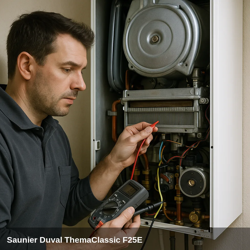
Fault codes related to sensors, electronics, gas valve, fan, or flue gas evacuation require a authorised technician with the appropriate equipment. If the same fault code reappears after a reset, or if the pressure drops repeatedly, a professional inspection is advisable. In Uniclima Do you find spare parts for the ThemaClassic range?
Frequently Asked Questions
Most lockouts are cleared by pressing the reset button on the panel. If the fault code reappears immediately, there is an underlying cause that should be diagnosed before persisting.
Between 1 and 1.5 bar when cold. Below 0.5 bar, the low pressure warning (F.21) appears, and above 2.7 bar, the high pressure warning (F.22) appears.
Those related to pressure (refill water), air in the circuit (bleed radiators), gas supply (check the valve), and reset after a temporary lockout. The rest, especially those involving sensors, electronics, and the gas valve, require an authorised technician.
Because the reset only unlocks the boiler, it does not correct the cause. If the code returns, there is a component or condition (leak, sensor, flue gas evacuation) that remains present and needs to be checked.