

Beretta Mynute 20 Ineco PCB Ref. R8353
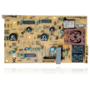
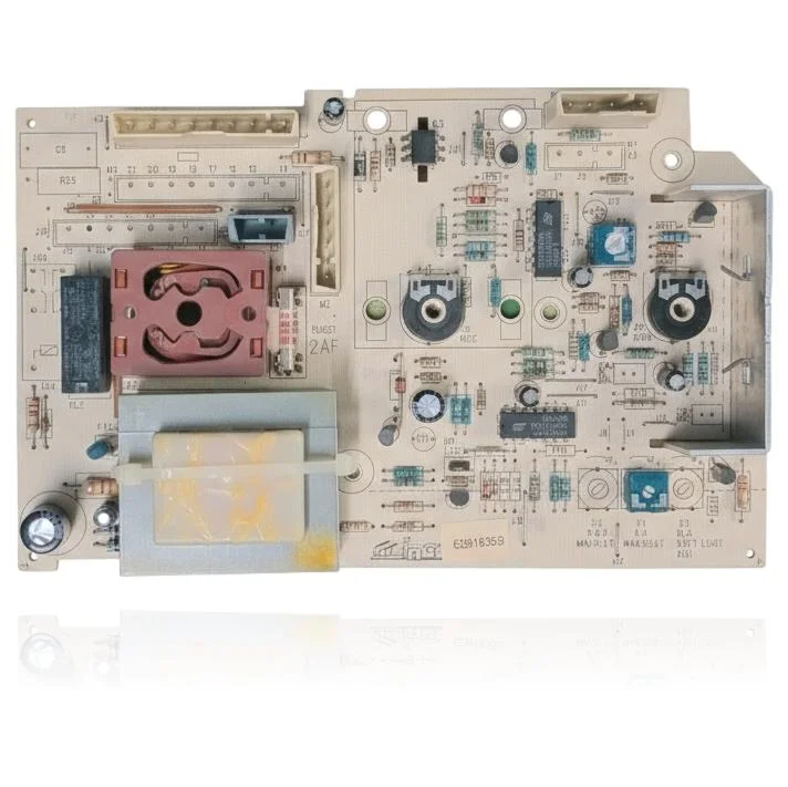
Control PCB for Beretta Mynute 20 and Mynute 20 CAP boilers. The circuit silkscreen shows the Ineco logo as the manufacturer, three adjustment trimmers (P1 maximum power, P2 minimum power, P3 soft start adjustment), and a 2A fast-acting fuse (FUSE1 2AF). Replacement requires first confirming the fault of the part through technical diagnosis, even when the control board stops functioning correctly.
- Type of part
- PCBs (control boards)
- Status
- Refurbished
- Catalogue reference
- R8353
- Warranty
- 1 year
Beretta boilers compatible with reference R8353
PCB with reference R8353. Two confirmed compatibilities: Mynute 20/20 (640353) and Mynute 20/20 CAP (640483).
Proven compatibility
| Boiler model | Family | Verification |
|---|---|---|
| Beretta Mynute 20/20 (640353) | Beretta Mynute 20/20 | Contrasted |
| Beretta Mynute 20/20 CAP (640483) | Beretta Mynute 20/20 | Contrasted |
Can't see your model or have questions? The printed reference takes precedence. How to check it · Send us a photo via WhatsApp.
How to check if the part number R8353 is the one for your boiler
The part reference, model, and equipment revision must be verified against the manufacturer's documentation.
- Find the reference printed on the installed part and check whether it matches the catalogue reference R8353. If it is not visible, do not identify the part from its shape alone.
- Check the full boiler model on its data plate and look for it in the model associations on this page.
- Compare the connections and physical body with the original part before installation.
- If anything is unclear, send us a photo of the marking via WhatsApp before placing your order.
Symptoms that require diagnosis on the PCB R8353
The PCB controls the ignition, modulation, and safety features of the boiler. These are the typical symptoms and what to do:
Common symptoms and faults
- 01
The boiler does not ignite and you suspect that the fuse on the PCB is damaged.
Cause: The PCB has a fast-acting fuse (2A) that protects the control circuit; if it blows, the boiler cannot ignite.
Visually inspect or measure with a multimeter the fuse FUSE1 (2A) before replacing the complete PCB.
- 02
The flame does not adjust properly between minimum and maximum power, it jumps or is always at maximum.
Cause: The trimmers P1 and P2 on this board regulate the maximum and minimum power; if they are misadjusted or damaged, the flame does not modulate correctly.
Before changing the PCB, check if someone has recently adjusted the trimmers P1/P2 or if a simple readjustment solves the problem.
- 03
The ignition is abrupt, without the usual gradual flame rise (the progressive ignition is failing).
Cause: The P3 trimmer on this PCB controls the soft ignition adjustment; if it fails, the boiler ignites abruptly or with backfiring.
Observe whether the abrupt ignition is constant or only occasional, and if it coincides with other electrical symptoms, before deciding to replace the PCB.
Beretta fault codes that require diagnosis
| Code | Fault | Technical checks |
|---|---|---|
| A01 | Permanent lockout of the boiler due to a fault in the ACF module (electronic flame control), indicated by the crossed-out flame symbol and a steady red LED. | The ACF module is the flame detection and control circuit integrated into the main PCB (R8353); when the PCB itself fails or the ACF module locks, A01 is triggered even if there is spark and gas. Verify: after pressing RESET, the lock reappears without a real combustion cause (electrode, gas, ionisation OK); inspect the PCB for burnt traces/components and check input/output voltages with a multimeter. |
These symptoms can have more than one cause. If your boiler displays a fault code, send it to us via WhatsApp along with a photo of the labeling, and we'll tell you if this is the part.
Data sheet for the Beretta R8353 PCB.
- Catalogue reference
- R8353
- Uniclima internal SKU
- PLABRTA22X
- Brand
- Beretta
- Type of part
- PCBs (control boards)
- Units in stock
- 1 unit
- Status
- Refurbished
- Warranty
- 1 year
- Shipping
- Delivery time shown at checkout
- Return
- 14 days
Part data and available documentation
Contrast the label codes, PCB, and revision with the installed part; they are not necessarily equivalent references.
- PCB manufacturer
- Ineco
- Fuse
- FUSE1, 2A fast acting (2AF)
- Trimmer P1
- Maximum power adjustment (MAX.HEAT)
- Trimmer P2
- Minimum power adjustment (MIN.HEAT)
- Trimmer P3
- Soft light adjustment (SOFT LIGHT ADJ.)
Manuals and technical documentation
Official documentation of the boiler, useful for locating the part and cross-referencing the fault codes.
- Beretta Mynute 20/20 CAP (640483) Manual (PDF) Document © Beretta, provided as a technical reference.
Frequently asked questions about the PCB R8353
Is this Ineco PCB Ref. R8353 suitable for the Beretta Mynute 20 CAP?
Who manufactures the R8353 PCB for the Beretta Mynute 20?
What fuse does the Mynute 20 PCB use and what is its amperage?
What are the functions of the trimmers P1, P2, and P3 on this PCB?
Spare parts related to Beretta Beretta Mynute 20/20