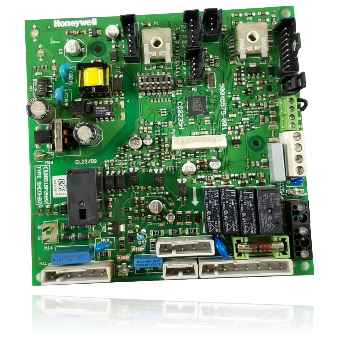
| F.61 | Error: gas valve control | The PCB controls the coils of the valve; if the driver/output on the board fails, a control error is detected. Check voltage and continuity to the valve and, if correct, replace the PCB. |
| F.62 | Error: gas valve disconnection controller | The control circuit of the valve is on the PCB; a fault in that stage can leave the valve powered or cut off late. Check the electrical closure after demand, and if the wiring/valve are OK, replace the PCB. |
| F.63 | Error: EEPROM | The EEPROM memory is integrated into the PCB; data corruption or memory IC failure triggers this code. Verify with parameter reset (d.96) and, if it reappears, replace the PCB. |
| F.64 | Fault: PCB / sensor / analog to digital transformer | The A/D converter and its inputs (NTC) reside on the PCB; if that electronics fail, F.64 is registered. Check NTC/wiring; if they are correct, the cause is the PCB. |
| F.65 | Error: electronics temperature too high | The thermal sensor on the PCB detects overheating or the circuit faults. Check for external causes (heat/ventilation) and, if it persists without reason, replace the PCB. |
| F.67 | Incorrect value returned by ASIC (flame signal) | The ASIC of the PCB interprets the ionisation; if the ASIC/flame channel fails, F.67 appears. Check for the presence of flame and ground; if they are correct, the PCB is the cause. |
| F.70 | Invalid product code (DSN) | The DSN/coding resides in the PCB; if the display and PCB are changed without readjusting the DSN, F.70 will trigger. Verify and reprogram the DSN according to the manual; if it is not corrected, recode or replace the PCB. |
| Connection | No communication between the main PCB and the user interface | The PCB manages communication with the UI; a bus/driver fault on the board triggers this alarm. Check connectors X32/X35 and 24 V; if the wiring is fine, replace the PCB. |