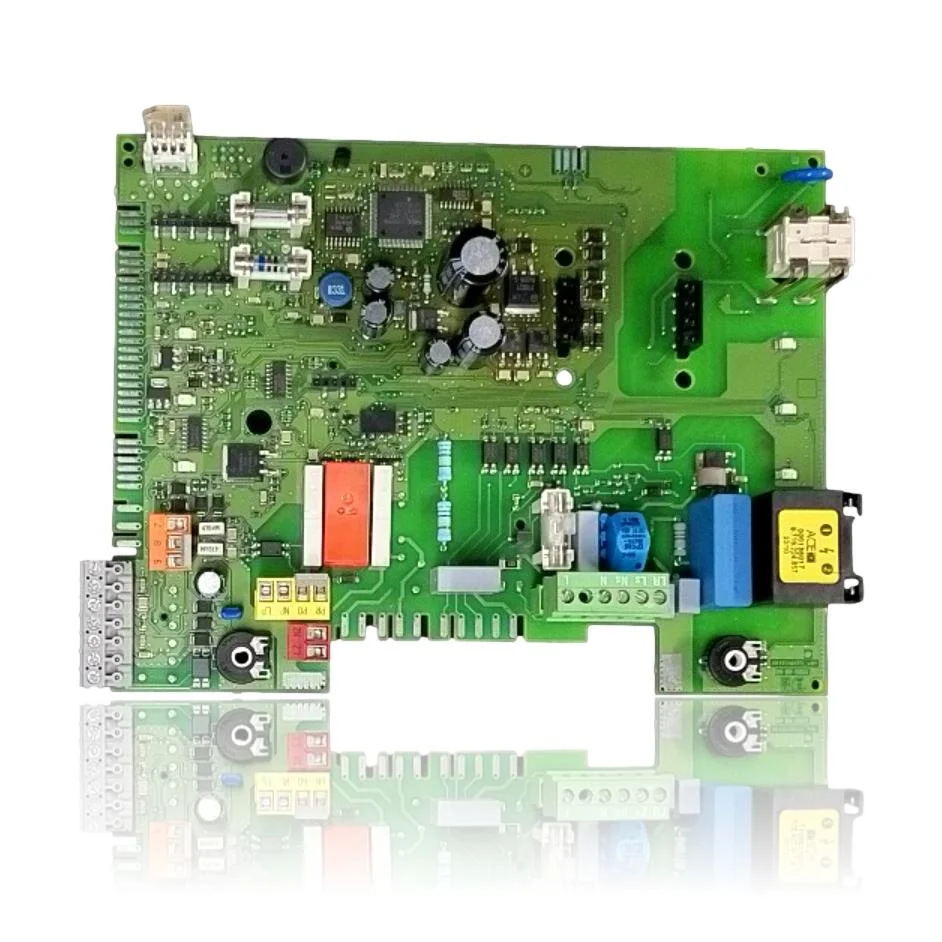
| F0 | Incorrect reference voltage (internal fault). | Fault in the reference/measurement of the Heatronic 3 (5 V/ADC) on the board causes F0; if after checks and retries it continues, the manufacturer advises replacing the board. Verify reference voltages and follow the manual's flow; if it persists, change the PCB. |
| A8 | BUS communication interrupted. | The BUS management (Heatronic 3) is on the PCB; a fault in the transceiver/micro or the PCB itself interrupts communication even with correct wiring/regulator. Check the BUS cable and regulator; if A8 persists, replace the PCB according to the manual. |
| b1 | Internal error or coding plug not detected/incorrect. | The encoder reads the input from the PCB; if that circuit fails, b1 appears even if the encoder is correct. Restore parameters and check the encoder; if b1 continues, the procedure requires changing the PCB. |
| F7 | Flame detected while the appliance is off (false flame). | The ionization stage on the PCB may leak (e.g., moisture on the PCB) and simulate a flame. Check electrodes/draught and ensure the PCB is not damp; if F7 persists, replace the PCB as indicated in the documentation. |
| Fd | The RESET button has been pressed by mistake (flashing). | If Fd does not disappear after resetting, the manual attributes it to an electronic fault (key detection/logic) of the Heatronic front panel. Retry the reset procedure; if the blinking persists, replace the PCB. |