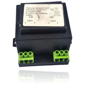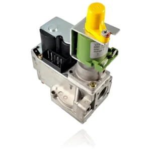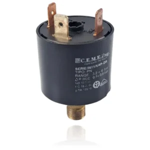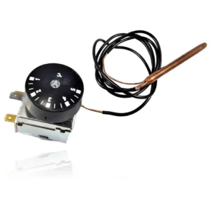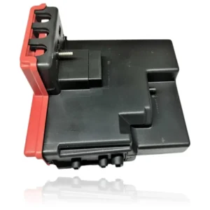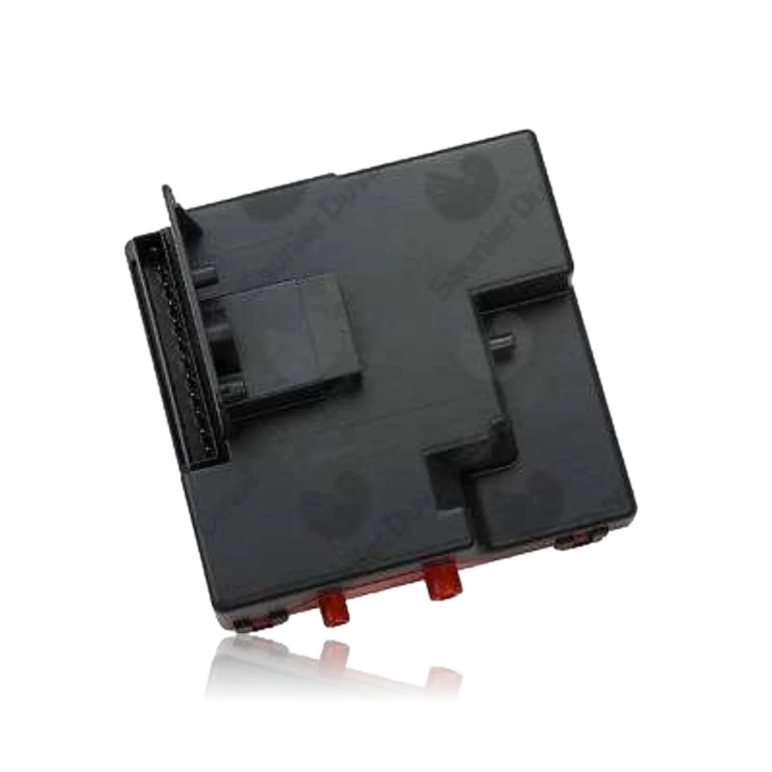
Saunier Duval Thelia Twin 28 E Ignition Control Board Ref. 05602400
Saunier Duval Thelia Twin 28 E features the Ignition Control PCB, an electronic component that manages the ignition, burner modulation, pump, and safety features of the boiler. When it fails, the boiler may not start, become locked, or exhibit erratic operation, displaying fault codes F.28 or F.29. This PCB is compatible with other models from the Thelia Twin, Themis Twin, Thelia, Sylva, and Master Twin ranges, among others. It should be replaced when these symptoms or fault codes are detected.
VAT included
Consult via WhatsAppSaunier Duval boilers compatible with reference 05602400
PCB with reference 05602400. Five confirmed compatibilities: Thelia Twin 28 E and Themis Twin 28 E.
Proven compatibility
| Boiler model | Family | Verification |
|---|---|---|
| Saunier Duval Thelia Twin 28 E | Thelia Twin | Contrasted |
| Saunier Duval Themis Twin 28 E | Themis Twin | Contrasted |
| Saunier Duval Thelia 30 E | Thelia | Contrasted |
| Saunier Duval Sylva 24 E | Sylva | Contrasted |
| Saunier Duval Master Twin L 85 E | Master Twin | Contrasted |
Can't see your model or have questions? The printed reference takes precedence. How to check it · Send us a photo via WhatsApp.
How to check if ref. 05602400 is the part for your boiler
What determines it is not the boiler model, but the reference printed on the part you already have installed.
- Find the reference printed on the installed part and check whether it matches the catalogue reference 05602400. If it is not visible, do not identify the part from its shape alone.
- Check the full boiler model on its data plate and look for it in the model associations on this page.
- Compare the connections and physical body with the original part before installation.
- If anything is unclear, send us a photo of the marking via WhatsApp before placing your order.
Symptoms and faults that the PCB 05602400 resolves.
The PCB controls the ignition, modulation, and safety features of the boiler. These are the typical symptoms and what to do:
Common symptoms and faults
- 01
The boiler does not ignite and the display is off.
Cause: The PCB controls the power supply and operation of the boiler; if it fails, nothing activates.
Measure the internal fuse and check that there is power at the input of the PCB before replacing it.
- 02
The boiler turns on, but the burner does not start and the other indicators are functioning correctly.
Cause: The circuit of the PCB that sends the ignition signal to the gas valve and the electrode is not operational.
Check that the gas valve and the ignition electrode work separately before considering that the PCB is faulty.
- 03
The remote control or the room thermostat cannot activate the boiler.
Cause: The communication module of the PCB with the external controller could be faulty.
Try to generate the demand directly from the boiler to determine if the problem is with the PCB or the control.
- 04
The boiler turns off by itself and operates intermittently, especially on humid days.
Cause: The PCB is protected by a plastic box; if moisture enters, it can cause occasional short circuits.
Disconnect the boiler, open the box, and check for condensation, rust, or water on the PCB.
Fault codes from Saunier Duval that this spare part resolves.
| Code | Fault | Diagnosis and solution |
|---|---|---|
| F.28 | Ignition fault of the burner | The burner does not ignite after five attempts. This may be due to a problem with the control board that prevents proper ignition. Check the gas supply and the condition of the PCB. |
| F.29 | Ignition fault of the burner | The burner does not ignite after five attempts. A fault in the control board may be the cause of this problem. Make sure that the gas is reaching properly and check the PCB. |
These symptoms can have more than one cause. If your boiler displays a fault code, send it to us via WhatsApp along with a photo of the labeling, and we'll tell you if this is the part.
Data sheet for the Saunier Duval 05602400 PCB.
- Catalogue reference
- 05602400
- Brand
- Saunier Duval
- Type of part
- PCBs (control boards)
- Units in stock
- 4 units
- Status
- Refurbished
- Warranty
- 1 year
- Shipping
- Delivery time shown at checkout
- Return
- 14 days
Manuals and technical documentation
Official documentation of the boiler, useful for locating the part and cross-referencing the fault codes.
- Saunier Duval THELIA TWIN 28 E Manual (PDF)Document © Saunier Duval, provided as a technical reference.
Frequently asked questions about the PCB 05602400
Is this encapsulated PCB compatible with the Thelia Twin 28 E?
Does this Saunier Duval PCB also work for a Master Twin L 85 E?
Spare parts related to Saunier Duval Thelia Twin