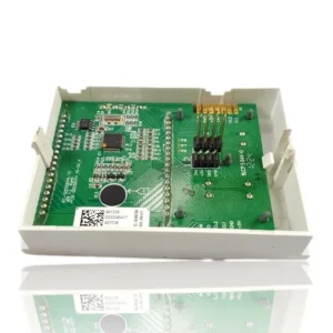


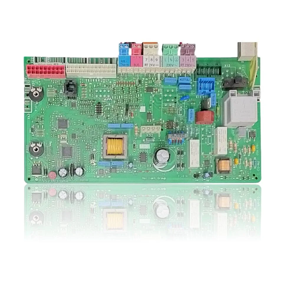
Vaillant Turbotec VMW 21/245/4-5 R3 PCB - Ref. 0020136649
The control PCB regulates the ignition, the modulation of the burner, the pump, and the safety features of the boiler. If it fails, the boiler may not start, become blocked, or operate erratically, potentially displaying fault codes such as F.27 or F.61. This component is compatible with several models in the VMW range, including the VMW 21/245/4-5 and the VMW 255/4-7, among others. A technician must confirm through diagnosis whether it needs to be replaced when these symptoms or associated fault codes occur. The manufacturer reference is 0020136649.
- Type of part
- PCBs (control boards)
- Status
- Refurbished
- Catalogue reference
- 0020136649
- Warranty
- 1 year
Vaillant boilers compatible with reference 0020136649
PCB with reference 0020136649. Five confirmed compatibilities: VMW 255/4-7 and VMW 255/4-7 R3.
Proven compatibility
| Boiler model | Family | Verification |
|---|---|---|
| Vaillant VMW 255/4-7 | VMW 255/4-7 (turboTEC/atmoTEC) | Contrasted |
| Vaillant VMW 255/4-7 R3 | VMW 255/4-7 (turboTEC/atmoTEC) | Contrasted |
| Vaillant VMW 21/245/4-5 | VMW 21/245/4-x | Contrasted |
| Vaillant VMW 21/245/4-3 R3 | VMW 21/245/4-x | Contrasted |
| Vaillant VMW 21/245/4-5 R3 | VMW 21/245/4-x | Contrasted |
Can't see your model or have questions? The printed reference takes precedence. How to check it · Send us a photo via WhatsApp.
How to check if ref. 0020136649 is the part for your boiler
The part reference, model, and equipment revision must be verified against the manufacturer's documentation.
- Find the reference printed on the installed part and check whether it matches the catalogue reference 0020136649. If it is not visible, do not identify the part from its shape alone.
- Check the full boiler model on its data plate and look for it in the model associations on this page.
- Compare the connections and physical body with the original part before installation.
- If anything is unclear, send us a photo of the marking via WhatsApp before placing your order.
Symptoms that require diagnosis on the PCB 0020136649
The PCB controls the ignition, modulation, and safety features of the boiler. These are the typical symptoms and what to do:
Common symptoms and faults
- 01
The boiler does not start at all, there is not even a pilot light on.
Cause: The PCB does not receive or distribute the power supply to its circuits.
Measure the voltage at the terminal block 230V~ L-N with a multimeter before replacing it.
- 02
The room thermostat connected to the BUS does not control anything; the boiler operates on its own.
Cause: The BUS communication port of the PCB has stopped working with the thermostat.
Check the continuity of the BUS cable between the control and the terminal block on the PCB before replacing the component.
- 03
A fault code is displayed on the screen that does not disappear even after resetting multiple times.
Cause: The control electronics maintain the lock because it continues to detect the same fault.
First, check if the code indicates an external component connected to that same terminal block (RT sensor, sensor).
- 04
The boiler goes through the ignition cycle but cuts off just before the flame appears.
Cause: The PCB does not send the opening command to the gas valve at the correct time.
Check that the wiring to the gas valve is not loose before blaming the PCB.
- 05
The 24V room thermostat connected to the boiler does not turn the heating on or off.
Cause: The RT 24V input on the PCB does not process the signal from the thermostat.
Do not bridge contacts or power components directly to test them. Request a technician to check the cause according to the model manual and its revision, without bypassing the protections. The symptom or fault code does not confirm on its own that this part is faulty.
Vaillant fault codes that require diagnosis
| Code | Fault | Technical checks |
|---|---|---|
| F.27 | Safety shutdown: flame detection error (flame simulation). | The PCB 0020136649 incorporates flame control; if its ionization/ASIC circuit is damaged (moisture/drift), it may interpret a non-existent flame. Check the ionization signal on the PCB and rule out electrode/cable and leaks in the gas valve. |
| F.61 | Gas valve activation/control error. | Gas driver/output fault on PCB 0020136649 prevents proper supply to the valve. Check voltage/signal from the PCB to the valve connector and rule out wiring and valve. |
| F.62 | Gas valve disconnection delay. | A defect in the electronics of PCB 0020136649 may keep the valve energized longer than necessary. Check that the closing signal from the PCB drops in time and that there is no parasitic light/defective valving. |
| F.63 | Fault: EEPROM (memory). | Corruption/read-write of the EEPROM on the PCB 0020136649. Confirm with diagnosis, attempt reprogramming/adjustment and, if it persists, replace the PCB. |
| F.64 | Error: electronics / sensor (A/D/NTC transformer). | Fault in the measurement electronics of PCB 0020136649 causes implausible NTC/analogue input readings. Check NTC/wiring and measure inputs on the PCB; if they are correct, the PCB is faulty. |
| F.65 | Error: electronics temperature too high. | Overheating or internal fault in the electronics of PCB 0020136649. Check ventilation/environment, temperature in the electronic box, and inspect the PCB for discolorations/damage. |
| F.67 | Fault: electronics/flame (flame signal not plausible). | Flame signal processing error by the electronics of PCB 0020136649. Check grounding, electrode/cable, and if ionisation is correct, replace PCB. |
| F.70 | Invalid product/appliance code (DSN). | After replacing the display and PCB 0020136649 simultaneously without reprogramming the DSN, the boiler enters F.70. Verify and enter the correct DSN in D.93 according to the model manual. |
These symptoms can have more than one cause. If your boiler displays a fault code, send it to us via WhatsApp along with a photo of the labeling, and we'll tell you if this is the part.
Data sheet for the PCB Vaillant 0020136649
- Catalogue reference
- 0020136649
- Uniclima internal SKU
- PECVTT21/245
- Brand
- Vaillant
- Type of part
- PCBs (control boards)
- Units in stock
- 4 units
- Status
- Refurbished
- Warranty
- 1 year
- Shipping
- Delivery time shown at checkout
- Return
- 14 days
Part data and available documentation
Contrast the label codes, PCB, and revision with the installed part; they are not necessarily equivalent references.
- PCB code (silkscreen)
- PM-03
- Connections of the terminal block (silkscreen)
- Labeled terminals: Anl-Therm, BUS, RT 24V (pins 7-8-9), 230V~ L-N, RT 230V~ (pins 3-4-5)
Manuals and technical documentation
Official documentation of the boiler, useful for locating the part and cross-referencing the fault codes.
- Vaillant VMW 21/245/4-5 manual (PDF) Document © Vaillant, provided as a technical reference.
Frequently asked questions about the PCB 0020136649
What code is printed on this PCB of the Turbotec VMW 21/245/4-5 R3?
Does this PCB work for a Vaillant VMW 255/4-7?
Is this PCB compatible with a VMW 21/245/4-3 R3?
How many models are compatible with the Vaillant Turbotec VMW 21/245/4-5 R3 PCB?
What fault codes are documented for this PCB?
What is the reference for the Vaillant Turbotec PCB?
Spare parts related to Vaillant VMW 21/245/4-x