






























































Short answer
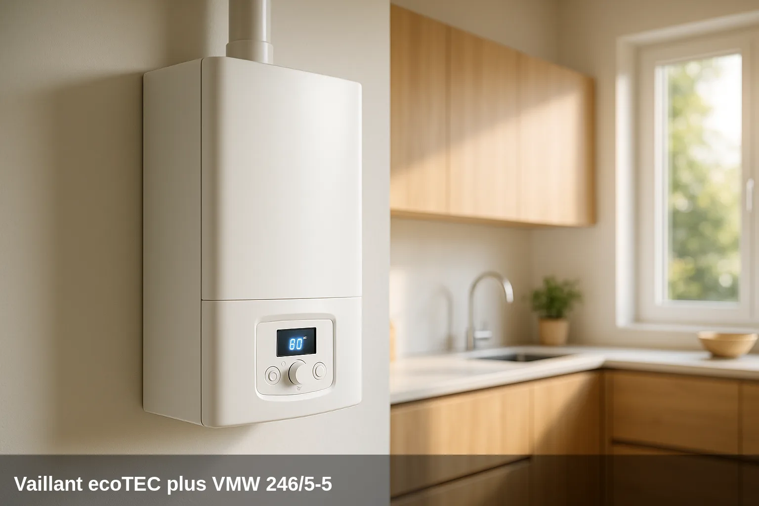
The Vaillant ecoTEC plus VMW 246/5-5 is a wall-mounted gas condensing boiler (heating and domestic hot water) with 20 kW for heating and 24 kW for hot water. It belongs to the ecoTEC plus family of the 5-5 generation and incorporates a 10-litre micro-storage for immediate hot water supply. The fault codes in the F.xx group are displayed on the boiler's screen and indicate a safety lockout that requires technical diagnosis. The VMW 296/5-5 and 346/5-5 models share the same error code logic as they belong to the same series.
Fault code table for the ecoTEC plus VMW 246/5-5
Quick summary of all fault codes. Below you have the details of each one with its cause and solution.
| Code | Meaning |
|---|---|
| F.00 | Interruption in the flow temperature sensor (open circuit) |
| F.01 | Interruption in the return temperature sensor (open circuit) |
| F.10 | Short circuit in the flow temperature sensor |
| F.11 | Short circuit in the return temperature sensor |
| F.13 | Short circuit in the hot start sensor or the accumulator sensor |
| F.20 | Safety shutdown due to activation of the temperature limiter |
| F.22 | Safety shutdown due to lack of water (insufficient pressure) |
| F.23 | Safety shutdown due to excessive temperature difference between flow and return |
| F.24 | Safety shutdown due to excessively rapid temperature rise |
| F.25 | Safety shutdown due to excessive flue gas temperature |
| F.26 | Fault in the gas valve (non-functional) |
| F.27 | Safety shutdown due to flame simulation (flame detected without ignition command) |
| F.28 | Fault during start-up: ignition failure |
| F.29 | Fault during operation: failed re-ignition after flame loss |
| F.32 | Fault in the fan (speed variation detected) |
| F.35 | Fault in the air intake or flue gas duct |
| F.42 | Fault in the coding resistor |
| F.49 | Fault in the eBUS (insufficient voltage or short circuit) |
| F.52 | Mass flow sensor (Venturi) connection fault |
| F.53 | Fault in the mass flow sensor (Venturi) |
| F.54 | Fault due to low gas pressure (associated with F.28 or F.29) |
| F.56 | Safety shutdown due to exceeding the CO limit value |
| F.57 | Fault in the safety comfort measurement program |
| F.61 | Fault in the gas valve control |
| F.62 | Fault in the gas valve shutdown delay |
| F.63 | Fault in the EEPROM (memory of the PCB) |
| F.64 | Fault in the electronics or sensors (short circuit detected in flow or return sensor) |
| F.65 | Fault due to overheating of the electronics |
| F.67 | Fault in the flame detector signal (signal out of limits or not plausible) |
| F.68 | Unstable flame signal during operation |
| F.70 | Invalid appliance code (Invalid DSN) |
| F.71 | Fault in the flow temperature sensor (implausible constant value) |
| F.72 | Fault in the flow or return sensor (excessive temperature difference) |
| F.73 | Fault in the water pressure sensor (signal too low, open circuit) |
| F.74 | Fault in the water pressure sensor (signal too high, short circuit) |
| F.75 | No change in pressure detected when the pump starts |
| F.76 | Activation of the primary heat exchanger overheat protection |
| F.77 | Fault in the flue damper or in the condensate pump |
| F.78 | Interruption in the DHW sensor (external controller) |
| F.83 | Fault due to lack of temperature change on start-up (temperature sensor) |
| F.84 | Temperature difference between sensors not plausible |
| F.85 | Incorrectly mounted temperature sensors |
| F.92 | Fault in the coding resistor (gas type) |
What can you check yourself?
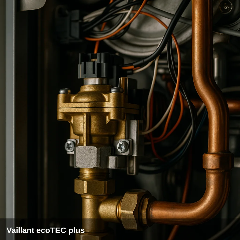
Some alerts can be resolved with simple and safe checks: replenishing the water pressure, bleeding the air from the radiators, checking that the gas valve is open, or resetting the boiler after a temporary lockout. If the code reappears after doing this, there is an underlying cause that should be reviewed by a qualified technician. Do not manipulate internal gas components nor electronics.
How to replenish the pressure step by step
- Locate the filling valve under the boiler.
- Open it slowly while observing the pressure gauge.
- Close the valve upon arrival at between 1 and 1.5 bar in cold.
- Bleed the radiators starting with the furthest one and check the pressure again.
- Reset the boiler; if the pressure warning disappears, the problem was resolved.
All fault codes and their solution
F.00 — Interruption in the flow temperature sensor (open circuit)
Why does it appear: Loose or incorrectly inserted NTC connector; poorly connected PCB multiple connector; wiring breakage; defective NTC sensor
What to do: Check and reconnect the flow sensor connector. If the wiring is in good condition and the fault persists, request replacement of the NTC sensor by an authorised technician.
Affected component: Temperature sensor
F.01 — Interruption in the return temperature sensor (open circuit)
Why does it appear: Loose or uninserted NTC connector; break in the wiring harness; defective NTC sensor
What to do: Check the connection of the return sensor connector. If the wiring is intact and the fault repeats, the sensor must be replaced by an authorized technician.
Affected component: Temperature sensor
F.10 — Short circuit in the flow temperature sensor
Why does it appear: NTC sensor fault; short circuit in the wiring harness or between cable and casing
What to do: Check the insulation of the wiring to the flow sensor. If a short circuit is confirmed or the sensor measures out of range, request replacement by an authorised technician.
Affected component: Temperature sensor
F.11 — Short circuit in the return temperature sensor
Why does it appear: NTC sensor fault; short circuit in the wiring harness or between cable and casing
What to do: Check the insulation of the wiring to the return sensor. If the short circuit is confirmed or the sensor measures out of range, request replacement by an authorised technician.
Affected component: Temperature sensor
F.13 — Short circuit in the hot start sensor or the storage tank sensor
Why does it appear: Cable in contact with the casing; NTC sensor faulty; defective connector
What to do: Check the insulation of the sensor cable. If the short circuit is confirmed, request replacement of the sensor by an authorised technician.
Affected component: Temperature sensor
F.20 — Safety shutdown due to activation of the temperature limiter
Why does it appear: Flow sensor not correctly connected thermally or faulty; grounding fault; the boiler does not perform the safety shutdown correctly.
What to do: Do not repeatedly reset without diagnosis. Request inspection of the flow sensor, grounding, and ignition system by an authorised technician.
Affected component: Temperature sensor
F.22 — Safety shutdown due to lack of water (insufficient pressure)
Why does it appear: Water pressure in the installation too low or zero; faulty pressure sensor; cable to the pump or pressure sensor loose or defective; pump blocked or faulty
What to do: Check the boiler's pressure gauge. If the pressure is below 1 bar, refill the system using the filling loop until it reaches between 1 and 1.5 bar. If the pressure is correct and the fault persists, request an inspection of the pressure sensor and the pump by an authorised technician.
Browse catalogue: Catalogue: spare parts · Vaillant
F.23 — Safety shutdown due to excessive temperature difference between flow and return
Why does it appear: Blocked or faulty circulation pump; insufficient minimum pump flow; supply and return sensors swapped; air in the circuit
What to do: Bleed the air from the heating circuit and check that the pressure is correct. If the fault persists, request a review of the pump and sensors by an authorised technician.
Affected component: Circulation pump
F.24 — Safety shutdown due to excessively rapid temperature rise
Why does it appear: Blocked circulation pump or insufficient minimum power; air in the appliance; water pressure too low; faulty gravity valve; NTC sensors poorly positioned or reversed
What to do: Bleed the circuit and check the installation pressure. If the fault repeats, request an inspection of the pump, sensors, and non-return valve by an authorised technician.
Affected component: Circulation pump
F.25 — Safety shutdown due to excessive flue gas temperature
Why does it appear: Optional gas safety thermostat disconnected; interruption in the plug connection or in the wiring harness
What to do: Check the connection of the flue thermostat and the condition of the wiring. Request inspection by an authorised technician.
Browse catalogue: Catalogue: heat exchangers · Vaillant
F.26 — Fault in the gas valve (non-functional)
Why does it appear: Stepper motor not connected; cable break; faulty stepper motor; electronic fault
What to do: Do not tamper with the gas valve. Request inspection of the connections and the gas valve by an authorised technician.
Browse catalogue: Catalogue: gas valves · Vaillant
F.27 — Safety shutdown due to flame simulation (flame detected without ignition command)
Why does it appear: Moisture in the electronics; defective flame detector; gas valve with internal leaks allowing gas flow without command
What to do: Do not reset without diagnosis. Request inspection of the gas valve and electronics by an authorised technician. It may involve a risk of gas leakage.
Browse catalogue: Catalogue: gas valves · Vaillant
F.28 — Fault in start-up: ignition failed
Why does it appear: Gas supply interrupted or insufficient pressure; faulty gas meter or flow control activated; air in the gas; dirty or faulty ignition electrode; blocked condensate pipe; incorrect gas nozzle; grounding fault
What to do: Check that the gas taps are open and that the gas supply is correct. If the fault persists after bleeding the gas, request an inspection of the ignition electrode, the condensate pipe, and the gas valve by an authorised technician.
Affected component: Ignition/Ionisation Electrode
F.29 — Fault during operation: failed re-ignition after flame loss
Why does it appear: Temporary interruption of gas supply; recirculation of combustion gases; obstructed condensate pipe; appliance grounding fault
What to do: Check the gas supply. If the fault occurs frequently, request an inspection of the condensate pipe, earthing, and the flue system by an authorised technician.
Affected component: Ignition/Ionisation Electrode
F.32 — Fault in the fan (speed variation detected)
Why does it appear: Fan plug disconnected or poorly inserted; connector on the PCB loose; fan mechanically blocked; Hall sensor faulty; defective wiring harness; electronics faulty
What to do: Request inspection of the fan, its connections, and the Hall sensor by an authorised technician.
Browse catalogue: Catalogue: flue fans · Vaillant
F.35 — Fault in the air intake or flue gas evacuation duct
Why does it appear: Air intake or flue gas outlet blocked or obstructed
What to do: Visually inspect the air intake and flue ducts for obstructions. Request inspection of the duct and fan by an authorised technician.
Browse catalogue: Catalogue: flue fans · Vaillant
F.42 — Fault in the coding resistor
Why does it appear: Short circuit or interruption in the power coding resistor or in the gas type resistor
What to do: Request review of the coding resistor and its connection by an authorised technician.
Browse catalogue: Catalogue: circuit boards · Vaillant
F.49 — Fault in the eBUS (insufficient voltage or short circuit)
Why does it appear: Short circuit in the eBUS; eBUS overload; presence of two power sources in the eBUS with opposite polarity
What to do: Check the wiring of the eBUS and the connected devices (thermostats, control boards). Request an electrical installation diagnosis by an authorised technician.
Affected component: Electrical installation
F.52 — Mass flow sensor (Venturi) connection fault
Why does it appear: Sensor not connected or plug poorly inserted
What to do: Request a review of the flow sensor connection by an authorised technician.
Affected component: Temperature sensor
F.53 — Fault in the mass flow sensor (Venturi)
Why does it appear: Low gas pressure; wet or blocked Venturi tube filter; faulty sensor; obstructed measurement point
What to do: Request a review of the Venturi sensor, its filter, and the gas pressure by an authorised technician.
Affected component: Temperature sensor
F.54 — Fault due to lack of gas pressure (associated with F.28 or F.29)
Why does it appear: No gas supply or insufficient gas inlet pressure; gas valve closed
What to do: Check that the gas valves are open and that there is supply in the network. If the supply is correct and the fault persists, request a review by an authorised technician.
Browse catalogue: Catalogue: gas valves · Vaillant
F.56 — Safety shutdown due to exceeding the CO limit value
Why does it appear: Defective combustion regulation component; incorrect contact on the gas valve
What to do: Do not reset without diagnosis. It may indicate a combustion problem. Request a combustion and gas valve inspection by an authorised technician.
Browse catalogue: Catalogue: gas valves · Vaillant
F.57 — Fault in the safety comfort measurement program
Why does it appear: The safety comfort system has detected a control error; severe corrosion on the ignition electrode.
What to do: Request inspection of the ignition electrode and the electronics by an authorised technician.
Affected component: Ignition/Ionisation Electrode
F.61 — Fault in the gas valve control
Why does it appear: Contact to ground or short circuit in the wiring harness to the gas valve; gas valve coils faulty (ground fault); electronics faulty
What to do: Do not tamper with the gas valve. Request inspection of the wiring harness and the gas valve by an authorised technician.
Browse catalogue: Catalogue: gas valves · Vaillant
F.62 — Fault in the gas valve shutdown delay
Why does it appear: The gas valve does not close in time after the shutdown command; leaking gas valve; faulty electronics
What to do: Request replacement of the gas valve and inspection of the electronics by an authorised technician.
Browse catalogue: Catalogue: gas valves · Vaillant
F.63 — Fault in the EEPROM (memory of the PCB)
Why does it appear: Internal electronics fault
What to do: Request replacement of the PCB by an authorised technician
Browse catalogue: Catalogue: circuit boards · Vaillant
F.64 — Fault in the electronics or sensors (short circuit detected in flow or return sensor)
Why does it appear: Short circuit in the flow or return temperature sensor; electronics faulty or overheated
What to do: Request a review of the flow and return NTC sensors and the PCB by an authorised technician.
Browse catalogue: Catalogue: circuit boards · Vaillant
F.65 — Fault due to overheating of the electronics
Why does it appear: External heat source affecting the electronics; electronics faulty
What to do: Check that there are no heat sources near the PCB. Request inspection by an authorised technician.
Browse catalogue: Catalogue: circuit boards · Vaillant
F.67 — Fault in the flame detector signal (signal out of limits or not plausible)
Why does it appear: Faulty electronics; flame detector signal not plausible
What to do: Request a review of the electronics and the flame detector by an authorised technician.
Browse catalogue: Catalogue: circuit boards · Vaillant
F.68 — Unstable flame signal during operation
Why does it appear: Air in the gas; insufficient gas pressure; incorrect air volume; blocked condensate duct
What to do: Check the gas supply. If the condensate pipe is blocked, unblock it. If the fault persists, request a combustion inspection by an authorised technician.
Affected component: Ignition/Ionisation Electrode
F.70 — Invalid appliance code (Invalid DSN)
Why does it appear: The display and the PCB have been replaced simultaneously without adjusting the specific appliance code; incorrect power coding resistor.
What to do: Request the appliance code (DSN) configuration by an authorised technician after replacement of electronic components.
Browse catalogue: Catalogue: circuit boards · Vaillant
F.71 — Fault in the flow temperature sensor (implausible constant value)
Why does it appear: Sensor improperly placed in the inlet duct; faulty flow temperature sensor
What to do: Request verification of the positioning and condition of the flow sensor by an authorised technician.
Affected component: Temperature sensor
F.72 — Fault in the flow or return sensor (excessive temperature difference)
Why does it appear: Flow or return temperature sensor fault; difference between both sensors out of tolerance
What to do: Request inspection and replacement of the affected sensor by an authorised technician.
Affected component: Temperature sensor
F.73 — Fault in the water pressure sensor (signal too low, open circuit)
Why does it appear: Connection with the water pressure sensor interrupted; short circuit in the sensor wiring; sensor internally faulty
What to do: Request inspection of the wiring and pressure sensor by an authorised technician.
Browse catalogue: Catalogue: spare parts · Vaillant
F.74 — Fault in the water pressure sensor (signal too high, short circuit)
Why does it appear: Short circuit in the sensor cable to the 5V or 24V supply; internal sensor fault
What to do: Request inspection of the wiring and replacement of the pressure sensor by an authorised technician.
Browse catalogue: Catalogue: spare parts · Vaillant
F.75 — No pressure change detected when the pump starts
Why does it appear: Water pressure sensor fault; pump fault; air in the heating system; insufficient water volume; expansion vessel not connected to the return
What to do: Bleed the system and check the pressure. If the pressure is correct and the fault persists, request a review of the pressure sensor and the pump by an authorised technician.
Browse catalogue: Catalogue: spare parts · Vaillant
F.76 — Activation of the primary heat exchanger overheat protection
Why does it appear: Cable or connection of the thermal fuse of the primary heat exchanger faulty; primary heat exchanger faulty
What to do: Request inspection of the thermal fuse and the primary heat exchanger by an authorised technician.
Browse catalogue: Catalogue: heat exchangers · Vaillant
F.77 — Fault in the flue gas flap or in the condensate pump
Why does it appear: The flue damper is not responding; condensate pump faulty or condensate pipe blocked
What to do: Check the condition of the condensate pipe. If it is blocked, unblock it. If a condensate pump is installed and the fault persists, request a review by an authorised technician.
Affected component: Circulation pump
F.78 — Interruption in the DHW sensor (external controller)
Why does it appear: External connection box VR65 connected to the combi boiler without bridging the domestic hot water NTC sensor
What to do: Request a review of the external controller configuration and the DHW sensor bridge by an authorised technician.
Affected component: Temperature sensor
F.83 — Fault due to lack of temperature change on start-up (temperature sensor)
Why does it appear: Insufficient water level in the appliance; temperature sensor improperly positioned
What to do: Check the installation pressure. If it is below 1 bar, refill. If the fault persists, request a review of the sensor by an authorised technician.
Affected component: Temperature sensor
F.84 — Temperature difference between sensors not plausible
Why does it appear: The flow and return sensors provide inconsistent values with each other; sensors inverted or incorrectly mounted.
What to do: Request verification of the positioning and connection of both sensors by an authorised technician.
Affected component: Temperature sensor
F.85 — Temperature sensors mounted incorrectly
Why does it appear: Are the flow sensor and the return sensor mounted on the same pipe or on the swapped pipes?
What to do: Request correction of the temperature sensors installation by an authorised technician.
Affected component: Temperature sensor
F.92 — Fault in the coding resistor (gas type)
Why does it appear: The coding resistance does not match the gas family configured on the PCB.
What to do: Request verification and adjustment of the gas type coding resistor by an authorised technician.
Browse catalogue: Catalogue: circuit boards · Vaillant
When to call a technician
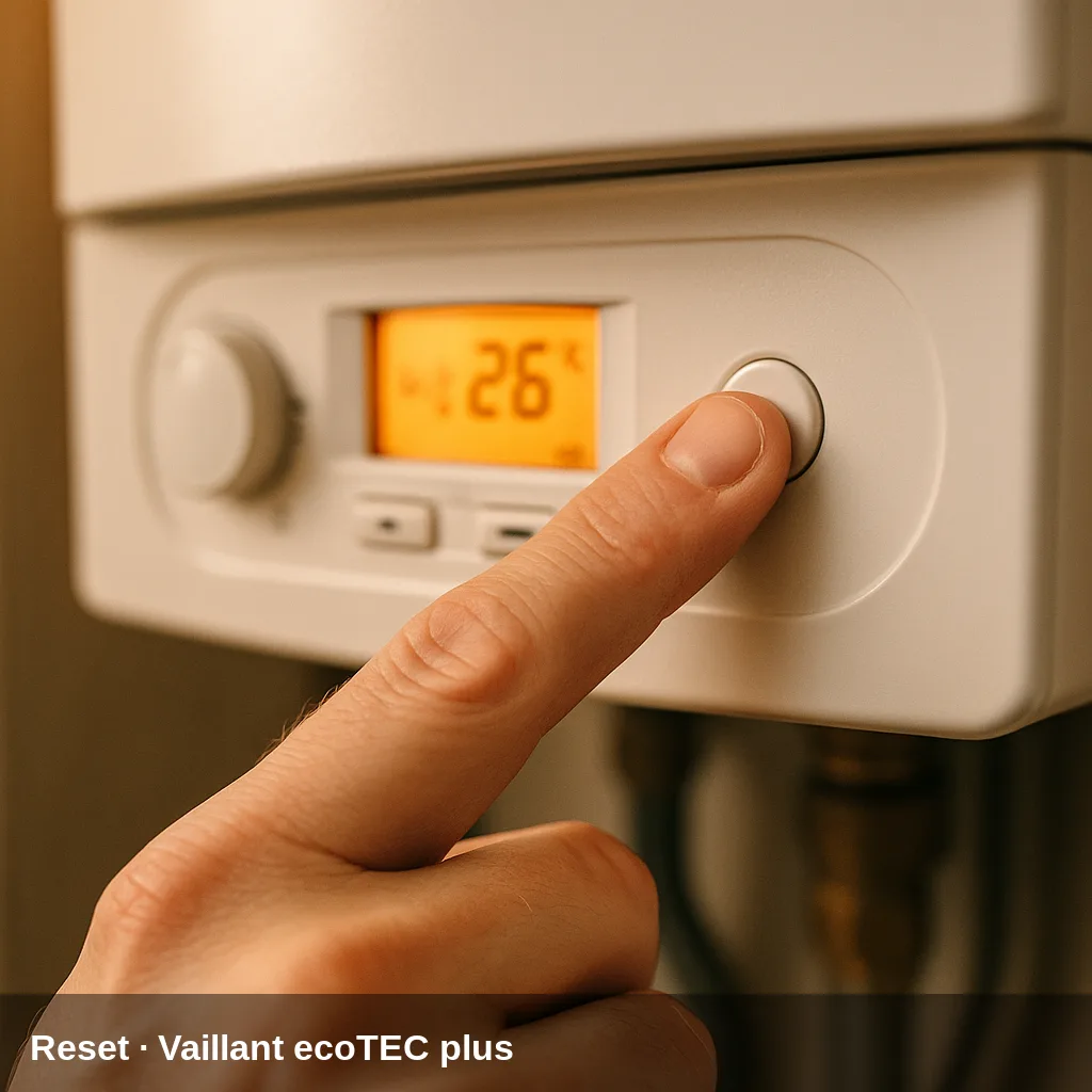
Fault codes related to sensors, electronics, gas valve, fan, or flue gas evacuation require a qualified technician with the appropriate equipment. If the same fault code reappears after a reset, or if the pressure drops repeatedly, a professional inspection is advisable. In Uniclima do you find spare parts for this boiler.
Frequently Asked Questions
Some specific lockouts like F.22 (low pressure) can be resolved by filling the system to 1-1.5 bar before resetting. For other F.xx codes, the reset should only be performed after identifying and correcting the cause, as repeatedly starting the boiler without diagnosis can worsen the fault or pose a risk. Contact an authorised Vaillant technician.
F.22 indicates that the boiler has detected insufficient water pressure in the heating circuit. Locate the boiler's pressure gauge (usually at the bottom): if it reads less than 1 bar, slowly open the filling valve until the pressure is between 1 and 1.5 bar, then close it. If the pressure drops recurrently, there may be a leak; request a technical inspection.
F.28 and F.29 indicate ignition failure or flame loss. The most common causes are: interrupted gas supply or closed gas valve, blocked condensate pipe, dirty or faulty ignition electrode. First, check that the gas supply is available. If it is correct, the inspection of the electrode and the condensate pipe requires an authorised technician.
F.73 indicates that the pressure sensor signal is too low (open circuit or defective sensor). F.74 indicates a signal that is too high (short circuit in the sensor wiring). F.75 means that when the pump starts, no pressure change is detected, which could be due to a faulty sensor, blocked pump, or air in the system. All three require diagnosis by an authorised technician.