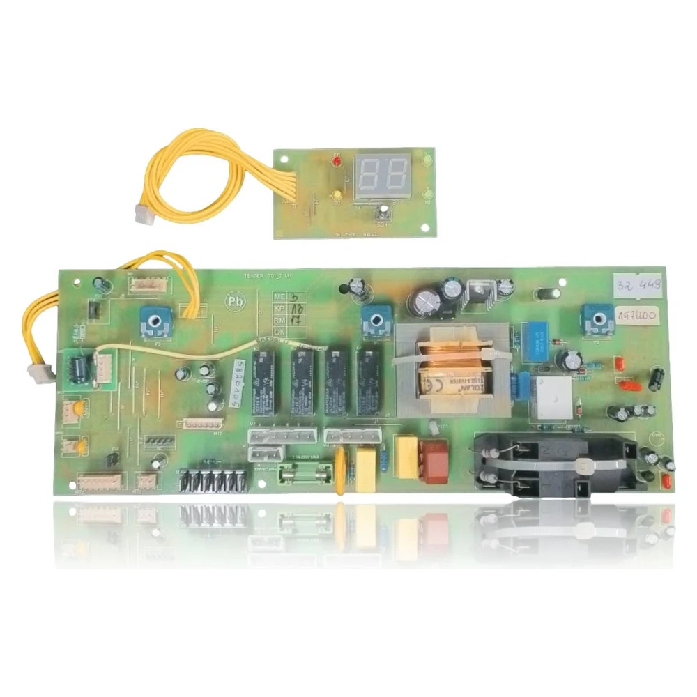
Main PCB + Tifell Ecomin 24 MT Display — Ref. 111112778
Refurbished set of the main PCB and the numeric display for Tifell Ecomin 24 MT. It controls ignition, fan, pump, gas valve, and sensors, manages safety features, and displays statuses/faults on the screen. Use it to replace a damaged board with symptoms of control failure or lack of ignition.
VAT included
Consult via WhatsAppTifell boilers compatible with reference 111112778
PCB with reference 111112778. Confirmed compatibility with two independent sources: Ecomin 24 MT.
Compatibility confirmed
| Boiler model | Family | Verification |
|---|---|---|
| Tifell Ecomin 24 MT | Ecomin | Confirmed · 2 sources |
Can't see your model or have questions? The printed reference takes precedence. How to check it · Send us a photo via WhatsApp.
How to check if the reference 111112778 is the part for your boiler.
What determines it is not the boiler model, but the reference printed on the part you already have installed.
- Array
- Array
- Array
- Array
- Array
- Array
- Array
Symptoms and faults that the PCB 111112778 resolves.
The PCB controls the ignition, modulation, and safety features of the boiler. These are the typical symptoms and what to do:
Common symptoms and faults
- 01
Display on but no start or spark
Cause: Control stage fault (relay/triac) or flame detection on PCB
Confirm 230 V~ at the input, voltage to the fan during pre-purge, spark at ignition, and ionization signal; check electrode wiring.
- 02
Pump and fan do not receive voltage with demand.
Cause: Auxiliary power supply/power stage of the faulty PCB
Measure output to pump/fan during demand; if 0 V with correct sensors, suspect PCB.
- 03
Spontaneous resets or flashing display
Cause: Instability in the power supply to the PCB or poor contact of the harness to the panel
Check neutral/live connections, ground, fuse, multi-pin connector on the PCB-panel, and the presence of stable 230 V~.
- 04
Communication error between panel and PCB
Cause: Damaged connection or interface cable of the PCB.
Inspect and replace the cable; if the issue persists with the new cable, the PCB is faulty.
- 05
Lockouts due to false flame detection
Cause: Current leak in the ionization circuit or drift at the PCB input.
Clean/replace the electrode and cable; if the signal remains out of range, check the ionization stage on the PCB.
- 06
Display off, boiler dead
Cause: Damaged fuse/primary of the PCB.
Check the fuse, presence of 230 V~ at the input terminals, and continuity; if okay and still no power, replace the PCB.
These symptoms can have more than one cause. If your boiler displays a fault code, send it to us via WhatsApp along with a photo of the labeling, and we'll tell you if this is the part.
Data sheet for the Tifell 111112778 PCB.
- OEM reference
- 111112778
- Brand
- Tifell
- Type of part
- PCBs (control boards)
- Units in stock
- 1 unit
- Status
- Refurbished
- Warranty
- 1 year
- Shipping
- 1-2 business days
- Return
- 14 days
Data read on the part and in the manufacturer's documentation
What we have not been able to verify does not appear here.
- Boiler compatibility
- Tifell Ecomin 24 MT (low NOx, sealed chamber)
- Power supply PCB
- 230 V ~ 50 Hz
- Controlled actuators
- Fan 230 VAC, pump 230 VAC, gas valve 230 VAC, 3-way valve 230 VAC
- DHW sensor
- NTC 10 kΩ @25 °C (B=3977), signal ≤5 VDC
- Fan (manual data)
- W961250060, 40 W 230 VAC
- Managed protections
- Overtemperature, flame detection by ionization, lack of flow/pressure switches, anti-freeze.
- Boiler dimensions
- 360 × 700 × 300 mm (width × height × depth)
- Useful heating power
- 12–24 kW (80/60 °C); thermal output 13.7–26.4 kW
- Visible references on PCB
- Internal labels: 32 449, 157400, 32 448, 497100 (not mapped to P/N Tifell)
- Cut off the electrical and gas supply before intervening. Lock and signal.
- Electrostatic discharge: use an ESD wrist strap and handle by the edges.
- Check the phase-neutral and ground polarity after installation.
- Replace the seals of the sealed chamber if the panel is opened; tightness and combustion testing is mandatory.
- Do not reuse damaged screws; moderate tightening torque to avoid cracks in the PCB and panel.
- Parameter P02 (gas) and P00 (power) after the change; record values.
- Bleed the hydraulic circuit and check the flow rate before ignition.
- Reset/start-up according to the manual; if faults persist, check peripherals before blaming the PCB.
Frequently asked questions about the PCB 111112778
Does this set work if only the display is faulty?
Do parameters need to be adjusted after changing the PCB?
My boiler is locking out without any codes on the display, could it be the PCB?