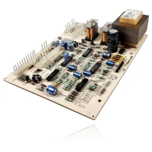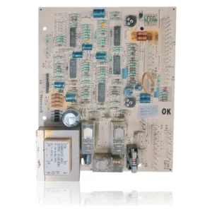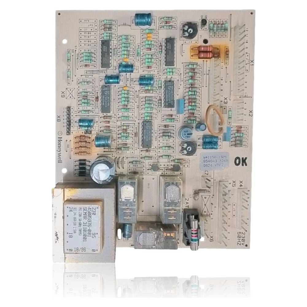
Ferroli NE Fluss 20 CE PCB (Honeywell W4115B1325 VMF7 M1) Ref. 39803410
Honeywell VMF7 M1 modulation PCB (W4115B1325) used by Ferroli as kit 39803410 in New Elite boilers, including the NE Fluss 20 CE. It manages ignition, flame detection by ionization, fan, pump, and safety. Refurbished product; please check the reference on your PCB label.
compatible with reference 39803410
PCB with reference 39803410. Five verified compatibilities: NE Fluss 20 CE and NE Fluss 20 PN CE.
Proven compatibility
| Boiler model | Family | Verification |
|---|---|---|
| Ferroli (FER) NE Fluss 20 CE | New Elite (NE) | Contrasted |
| Ferroli (FER) NE Fluss 20 PN CE | New Elite (NE) | Contrasted |
| Ferroli (FER) NE Fluss 20 EL PN CE | New Elite (NE) | Contrasted |
| Ferroli (FER) NE TF 120 EL (CE) | New Elite (NE) | Contrasted |
| Ferroli Master CE 20 MEL | Master | Contrasted |
Can't see your model or have questions? The printed reference takes precedence. How to check it · Send us a photo via WhatsApp.
How to check if the ref. 39803410 is the part for your boiler
What determines it is not the boiler model, but the reference printed on the part you already have installed.
Symptoms and faults that the PCB 39803410 resolves.
The PCB controls the ignition, modulation, and safety features of the boiler. These are the typical symptoms and what to do:
Common symptoms and faults
- 01
Random lockouts with red LED and need for manual reset
Cause: Intermittent fault in the VMF7 electronics (relays, cold solder joints, auxiliary power supply) or unstable flame detection
Check stable power supply 230 V~, continuity of the 2AT fuse on the PCB, condition of ground connections and electrodes; verify that the reset temporarily restores operation.
- 02
There is no ignition spark even with demand.
Cause: Ignition stage in the PCB or faulty spark cable/transformer
Check for voltage presence at the ignition transformer during the attempt; inspect wiring and electrode; if there is no command from the PCB, a fault in the module is likely.
- 03
Fan or pump does not start despite demand.
Cause: Output from control board in fatigued board or blocked relay
Check that the PCB outputs voltage to the motor/fan according to the diagram; check the air pressure switch and thermostats in series before blaming the PCB.
- 04
Failed ignitions with immediate lockout
Cause: No ionization detection (mass chain/electrode/PCB) or faulty flame management in the VMW 242.
Clean the electrode and burner, check the ionization and ground cable; measure the ionization current with a microammeter; if it persists, suspect the flame control stage of the PCB.
- 05
Spot overheating and safety trip
Cause: Incorrect modulation or abnormal pump/fan control by PCB
Check hydraulic circuit (flow, bleeding) and pump operation; if conditions are correct and the issue persists, evaluate the PCB.
These symptoms can have more than one cause. If your boiler displays a fault code, send it to us via WhatsApp along with a photo of the labeling, and we'll tell you if this is the part.
Technical sheet: Ferroli (FER) 39803410
- Catalogue reference
- 39803410
- Brand
- Ferroli
- Type of part
- PCBs (control boards)
- Units in stock
- 0 units
- Status
- Refurbished
- Warranty
- 1 year
- Shipping
- Delivery time shown at checkout
- Return
- 14 days
Data read on the part and in the manufacturer's documentation
What we have not been able to verify does not appear here.
- OEM reference Ferroli
- 39803410 (replaces 38316700/38316710/38316711).
- Component manufacturer
- Honeywell/Resideo, VMF7 M1 series.
- Component model
- W4115B1325 / W4115B1325B. ([verrino.it](https://www.verrino.it/products/21660?utm_source=openai))
- Power supply
- 230 V~ 50 Hz; fuse on PCB 2AT (according to silkscreen).
- Verified compatibility
- NE Fluss 20 CE, NE Fluss 20 PN CE, NE Fluss 20 EL PN CE, Master CE 20 MEL, NE TF 120 EL (CE).
- Market
- NE "Fluss" models present/homologated in Spain.
- Adjustment observations
- NE models integrate adjustment potentiometers in the control panel; adjust according to the service manual after changing the PCB.
- Cut off the electrical power and close the gas before intervening.
- Discharge capacitors and avoid ESD when handling the PCB.
- Check for gas tightness after any gas disconnection.
- Bleed the hydraulic circuit and the combustion circuit correctly.
- Respect torque values on connections and terminals.
- Use new single-use gaskets where applicable.
- Check and, if applicable, readjust potentiometers/parameterization after the change according to the manual.
- The manual reset should not be used to mask combustion or ventilation faults.
Frequently asked questions about the PCB 39803410
Is it compatible with my Ferroli NE Fluss 20 CE without a display?
My PCB says W4115B1325B, is it valid?
What happens if my boiler shows only a fixed red LED?
Spare parts related to Ferroli (FER) New Elite (NE)