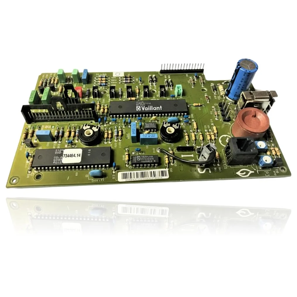
| F.61 | Gas valve activation error. | The relay/output stage of the PCB (auxiliary/main) does not correctly switch the gas valve. Check the power supply to the valve at the terminals, continuity of the harness, and if everything is correct, replace the PCB to confirm. |
| F.62 | Delay in gas valve disconnection. | The PCB keeps the gas valve energized longer than it should (control/relay fault). Check that the valve closes properly and that the wiring is correct; if the issue persists, measure the control voltage and confirm by replacing the PCB. |
| F.63 | Fault: EEPROM (electronics). | Corruption/defect of the EEPROM memory on the PCB. Check resets and parameters; the standard check is to replace the board with a new or programmed one to rule out the fault. |
| F.64 | Fault in the electronics/NTC. | Fault in the measurement/ADC stage or sensor power supply on the PCB. Check NTC and wiring; if the sensors measure correctly but the fault code persists, the cause is the PCB. |
| F.65 | Fault: electronics temperature too high. | The thermal sensor on the PCB detects overheating or the PCB itself is damaged. Check ventilation/location and temperatures; if they are normal and the error repeats, replace the PCB. |
| F.67 | Fault: electronics/flame (flame signal not plausible). | The detection/ionization stage on the PCB delivers an incoherent signal. Check the electrode, cable, and polarity; if everything is correct, the fault is in the PCB. |