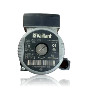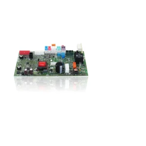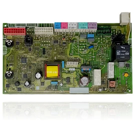
Vaillant Ecotec Plus VMW ES 296 3 5 R3 control board Ref. 0020092478
When you turn on the hot water tap, the Vaillant Ecotec Plus VMW ES 296 3 5 R3 PCB (control board) comes into action to control the ignition and modulation of the burner, as well as the pump and safety features of the boiler. If this board fails, the boiler may not start, become locked, or exhibit erratic behavior. You may notice issues such as fault code F.61, which indicates that the gas valve is not receiving the ignition command, or F.64, which indicates that the board is misreading the temperature sensors. This part is compatible with models such as VMW 296/3-5 R3 and VMW 346/3-5, among others. It is recommended to replace it when there are ignition failures or general operational issues with the boiler.
VAT included
Consult via WhatsAppVaillant boilers compatible with reference 0020092478
PCB with reference 0020092478. 11 verified compatibilities: VMW 296/3-5 and VMW 296/3-5 R3.
Proven compatibility
| Boiler model | Family | Verification |
|---|---|---|
| Vaillant VMW 296/3-5 | ecoTEC plus VMW (combi) | Contrasted |
| Vaillant VMW 296/3-5 R3 | ecoTEC plus VMW (combi) | Contrasted |
| Vaillant VMW 296/3-5 R5 | ecoTEC plus VMW (combi) | Contrasted |
| Vaillant VMW 346/3-5 | ecoTEC plus VMW (combi) | Contrasted |
| Vaillant VMW 346/3-5 R3 | ecoTEC plus VMW (combi) | Contrasted |
| Vaillant VMW 346/3-5 R5 | ecoTEC plus VMW (combi) | Contrasted |
| Vaillant VM 246/3-5 | ecoTEC plus VM (heating only) | Contrasted |
| Vaillant VM 246/3-5 R3 | ecoTEC plus VM (heating only) | Contrasted |
| Vaillant VM 376/3-5 | ecoTEC plus VM (heating only) | Contrasted |
| Vaillant VM 376/3-5 R3 | ecoTEC plus VM (heating only) | Contrasted |
| Vaillant VM 376/3-5 R5 | ecoTEC plus VM (heating only) | Contrasted |
Can't see your model or have questions? The printed reference takes precedence. How to check it · Send us a photo via WhatsApp.
How to check if ref. 0020092478 is the part for your boiler
What determines it is not the boiler model, but the reference printed on the part you already have installed.
- Find the reference printed on the installed part and check whether it matches the catalogue reference 0020092478. If it is not visible, do not identify the part from its shape alone.
- Check the full boiler model on its data plate and look for it in the model associations on this page.
- Compare the connections and physical body with the original part before installation.
- If anything is unclear, send us a photo of the marking via WhatsApp before placing your order.
Symptoms and faults that the PCB 0020092478 resolves.
The PCB controls the ignition, modulation, and safety features of the boiler. These are the typical symptoms and what to do:
Common symptoms and faults
- 01
The boiler is completely off: no pilot lights or display are turning on.
Cause: The PCB does not start up, so the unit shows no signs of life.
Before replacing the PCB, check that it is receiving 230 V and that its internal fuse is intact.
- 02
The pump or the fan do not start even though the boiler is calling for heat.
Cause: The PCB does not send the command to start up.
Feed the pump or the fan directly with a jumper to see if they work on their own. If they do, the suspect is the PCB.
- 03
The PCB has some burnt areas, or it smells burnt when opening the boiler.
Cause: A short circuit or a voltage surge has damaged components or traces on the PCB.
Check the fuses and relays at a glance, and verify the differential of the house in case there is an electrical leak.
- 04
After a power outage, the boiler loses the time programming you had set.
Cause: The PCB does not retain data because its backup battery or internal memory is faulty.
If the PCB has a backup battery, replace it first before declaring the board faulty.
Fault codes from Vaillant that this part resolves.
| Code | Fault | Diagnosis and solution |
|---|---|---|
| F.61 | The gas valve does not receive the ignition signal. | When the boiler requests heat, the PCB should supply power to the gas valve to open it, but it doesn't. To check this: measure if there is voltage at the terminals of the valve when the boiler starts. If the wiring and the valve are fine but the command does not arrive, or arrives intermittently, the PCB is faulty and needs to be replaced. |
| F.62 | The gas valve does not close when the boiler is turned off. | When the boiler turns off, the PCB should cut the power to the gas valve, but it gets 'stuck' and keeps it open. It is almost always a fault of the relay on the PCB. To check this: see if the valve stops receiving voltage right when the flame goes out; if it continues to receive power and only closes when you disconnect it manually, the PCB is the cause and needs to be replaced. |
| F.63 | Fault in the internal memory of the PCB (EEPROM) | The PCB stores its settings in internal memory (EEPROM) and is unable to read it properly. First, try cutting the power to the boiler for one minute and then turning it back on. If the error reappears, the memory of the PCB is damaged: it needs to be reprogrammed or, more commonly, the PCB needs to be replaced. |
| F.64 | The PCB reads the temperature sensors incorrectly. | The boiler thinks that a temperature sensor (NTC) is short-circuited even though it is actually fine. To clarify: measure the resistance of the sensors, both at the sensor itself and at the connector on the PCB. If the values are correct and the fault persists, the fault is within the board and it needs to be replaced. |
| F.65 | The PCB is overheating. | The PCB detects too much temperature inside itself, or the sensor monitoring it is faulty. Check that the boiler is ventilating properly and that there is no heat source close to the electronics. If the surrounding temperature is normal and the fault persists, the PCB is faulty. |
| F.67 | The PCB does not properly recognize the flame. | The circuit of the PCB that monitors the flame receives a signal that doesn't match. Check the ionization electrode and its cable: condition, connection, and ensure they are not dirty or worn. If they are fine and the fault persists, the part of the PCB that detects the flame is faulty and needs to be replaced. |
| F.70 | The device code (DSN) does not match. | It usually occurs when the display or the PCB has been changed without reprogramming the device code (DSN), or when the installed PCB does not match the power of that boiler. A technician can adjust the DSN from the service menu; if it is not possible, the correct PCB for that model must be installed and configured. |
These symptoms can have more than one cause. If your boiler displays a fault code, send it to us via WhatsApp along with a photo of the labeling, and we'll tell you if this is the part.
Data sheet for the Vaillant PCB 0020092478.
- Catalogue reference
- 0020092478
- Brand
- Vaillant
- Type of part
- PCBs (control boards)
- Units in stock
- 4 units
- Status
- Refurbished
- Warranty
- 1 year
- Shipping
- Delivery time shown at checkout
- Return
- 14 days
Data read on the part and in the manufacturer's documentation
What we have not been able to verify does not appear here.
- Confirmed boiler models for reference 0020092478
- Vaillant VMW ES 296/3-5 R3 (and compatible models VMW ES 346/3-5, VM 376/3-5)
Frequently asked questions about the PCB 0020092478
Is this PCB Ref. 0020092478 suitable for a Vaillant Ecotec Plus VMW ES 296/3-5 R3?
Spare parts related to Vaillant ecoTEC plus VMW (combi)