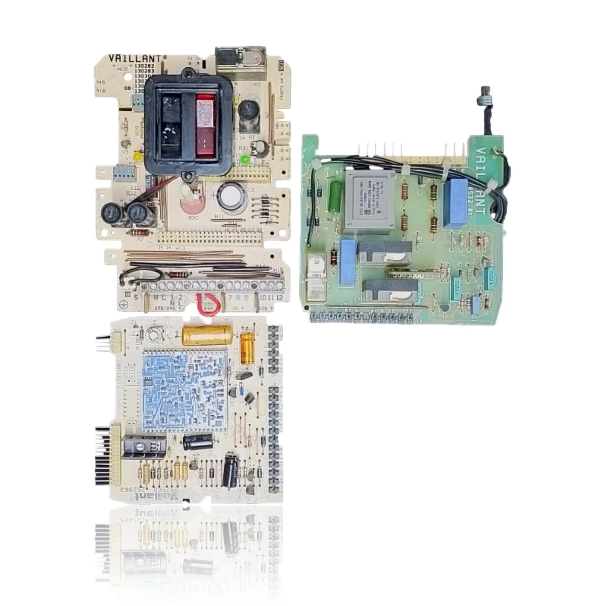
| F.61 | Fault: gas valve control (does not activate correctly). | Faults in the driver/output of the PCB to the valve (triac/relay) cause absence of signal or short circuit. Check voltage and signal at the valve connectors during start-up and continuity of the harness; if the valve/wiring are correct, the PCB is the cause. |
| F.62 | Fault: gas valve disconnection delay (late closure). | A fault in the PCB output circuit can keep the valve energized and delay its closure. Check that the valve closes mechanically and measure that the PCB cuts the power supply in time; if the valve responds and the delay persists, the PCB is defective. |
| F.63 | Error: EEPROM (fault in the electronics). | Corruption or fault in the PCB memory prevents correct start-up/operation. After reset and voltage verification, if the error persists, replace the PCB. |
| F.64 | Fault: PCB/sensor/A/D converter. | Analog/A-D channel fault of the PCB simulates a short circuit in the flow/return NTC. Check the NTCs and the harness for ohmic values; with correct sensors, the cause is the PCB. |
| F.65 | Fault: electronics temperature too high. | The internal sensor/thermal management of the PCB detects overheating or a defect in the electronic module. Check ventilation and dissipation in the electronic box; if conditions are normal and the error persists, the PCB is damaged. |
| F.67 | Fault: electronics/flame (flame signal not plausible). | Fault in the flame evaluation circuit/ASIC of the PCB causes incorrect ionization reading. Check ionization electrode, wiring, and grounding; if they are correct, the PCB is responsible. |
| F.70 | Invalid product code (DSN/coding). | Replacement of the display and PCB without recoding or incorrect coding resistor on the board. Verify/load the equipment identification (DSN) and the coding resistor; if it does not support configuration, replace the PCB. |