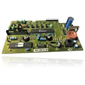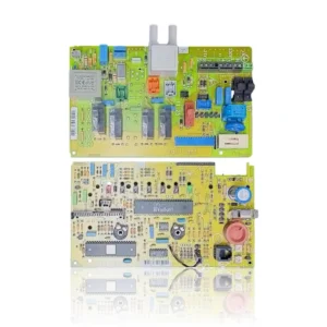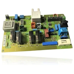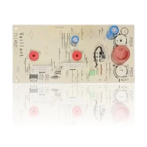


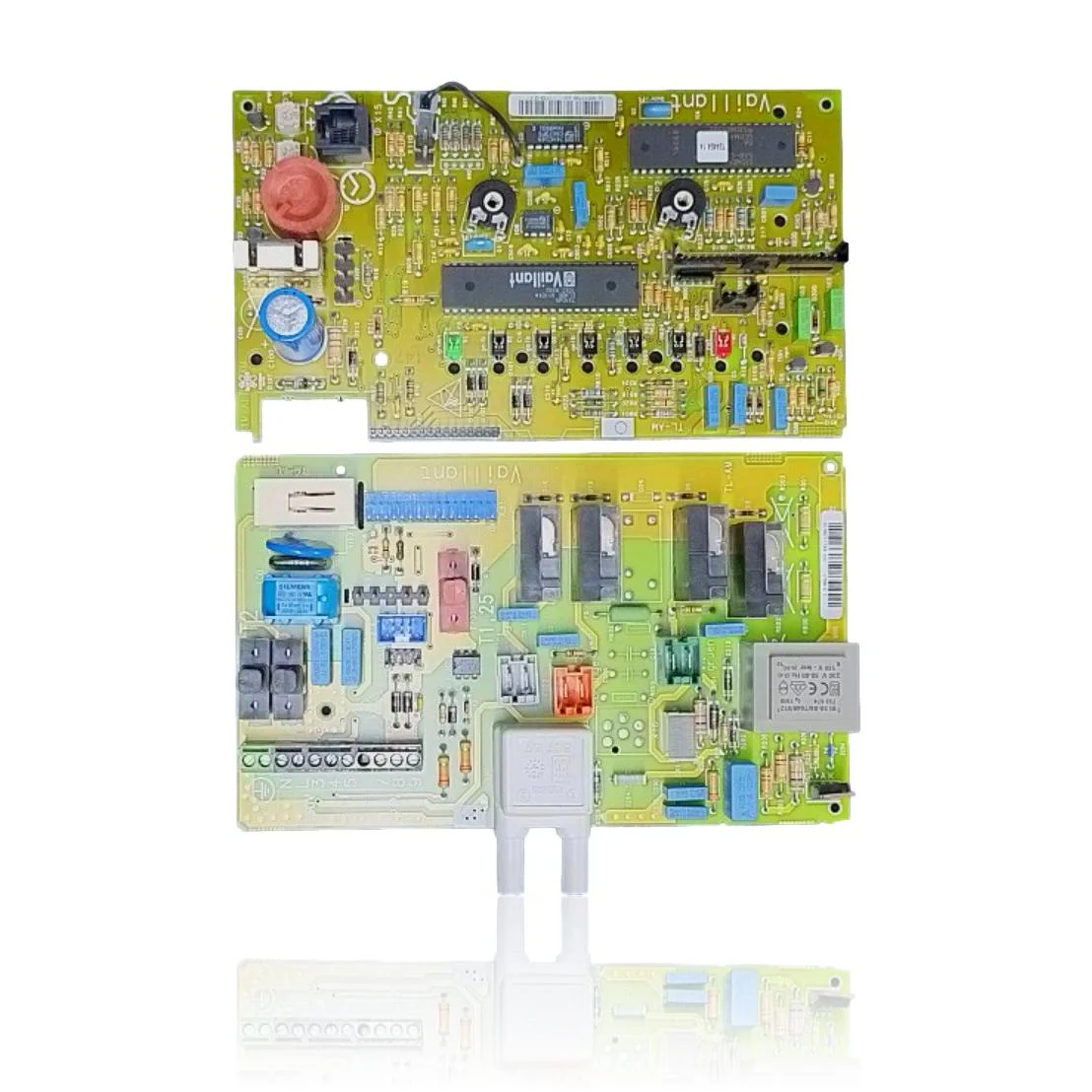
PCB for Vaillant Boilers VC, VCM, VU, and VUW (series /1)
Control PCB for Vaillant boilers of the /1 series (VC, VCM, VU, and VUW). It includes the transformer that reduces the mains voltage to 21V for the secondary circuit, protected by a 1.25A fuse. It is responsible for the overall operation of the unit. The replacement requires first confirming the fault of the part through technical diagnosis, even when the boiler does not ignite, does not respond, or shows electronic faults.
- Type of part
- PCBs (control boards)
- Status
- Refurbished
- Catalogue reference
- 130438
- Warranty
- 1 year
Vaillant boilers compatible with reference 130438
PCB with reference 130438. Eight confirmed compatibilities: VCM 182/1 E and VCM 242/1 E.
Proven compatibility
| Boiler model | Family | Verification |
|---|---|---|
| Vaillant VCM 182/1 E | Turboblock VCM (series /1 E) | Contrasted |
| Vaillant VCM 242/1 E | Turboblock VCM (series /1 E) | Contrasted |
| Vaillant VCM 282/1 E | Turboblock VCM (series /1 E) | Contrasted |
| Vaillant VCM 240/1 | Turboblock VCM (series /1 E) | Contrasted |
| Vaillant VCM 260/1 | Turboblock VCM (series /1 E) | Contrasted |
| Vaillant VCM 180/1 | Turboblock VCM (series /1 E) | Contrasted |
| Vaillant VC 240/1 | VC (series /1 E) | Contrasted |
| Vaillant VC 242/1 E | VC (series /1 E) | Contrasted |
Can't see your model or have questions? The printed reference takes precedence. How to check it · Send us a photo via WhatsApp.
How to check if ref. 130438 is the part for your boiler
The part reference, model, and equipment revision must be verified against the manufacturer's documentation.
- Find the reference printed on the installed part and check whether it matches the catalogue reference 130438. If it is not visible, do not identify the part from its shape alone.
- Check the full boiler model on its data plate and look for it in the model associations on this page.
- Compare the connections and physical body with the original part before installation.
- If anything is unclear, send us a photo of the marking via WhatsApp before placing your order.
Symptoms that require diagnosis on the PCB 130438
The PCB controls the ignition, modulation, and safety features of the boiler. These are the typical symptoms and what to do:
Common symptoms and faults
- 01
The boiler does not ignite or respond to any controls, as if it has no power.
Cause: If the transformer on the PCB does not deliver 21V to the secondary circuit, all the electronics will be without power and nothing will start.
Measure with a multimeter if the 1.25A fuse has blown before declaring the PCB dead.
- 02
The display is completely off, with no indicators or lights on.
Cause: It is the typical signal that the secondary fuse has blown and has cut off the power to the control part.
Check if the fuse is visibly burnt or measure its continuity before replacing the PCB.
- 03
An error code related to the PCB (control board) is displayed on the screen.
Cause: The control board itself detects an internal management fault and displays it instead of starting the burner.
Note the exact code and try a reset of the boiler; some faults of this type recover on their own.
Vaillant fault codes that require diagnosis
| Code | Fault | Technical checks |
|---|---|---|
| F.61 | Gas valve activation error. | The relay/output stage of the PCB (auxiliary/main) does not correctly switch the gas valve. Check the power supply to the valve at the terminals, continuity of the harness, and if everything is correct, replace the PCB to confirm. |
| F.62 | Delay in gas valve disconnection. | This symptom may be related to the part, but it does not confirm that it is faulty. A technician must check the equipment and its inspection according to the manual before deciding on a repair or replacement. |
| F.63 | Fault: EEPROM (electronics). | Corruption/defect of the EEPROM memory on the PCB. Check resets and parameters; the standard check is to replace the board with a new or programmed one to rule out the fault. |
| F.64 | Fault in the electronics/NTC. | Fault in the measurement/ADC stage or sensor power supply on the PCB. Check NTC and wiring; if the sensors measure correctly but the fault code persists, the cause is the PCB. |
| F.65 | Fault: electronics temperature too high. | The thermal sensor on the PCB detects overheating or the PCB itself is damaged. Check ventilation/location and temperatures; if they are normal and the error repeats, replace the PCB. |
| F.67 | Fault: electronics/flame (flame signal not plausible). | The detection/ionization stage on the PCB delivers an incoherent signal. Check the electrode, cable, and polarity; if everything is correct, the fault is in the PCB. |
These symptoms can have more than one cause. If your boiler displays a fault code, send it to us via WhatsApp along with a photo of the labeling, and we'll tell you if this is the part.
Data sheet for the Vaillant 130438 PCB.
- Catalogue reference
- 130438
- Uniclima internal SKU
- PEVTES242
- Brand
- Vaillant
- Type of part
- PCBs (control boards)
- Units in stock
- 5 units
- Status
- Refurbished
- Warranty
- 1 year
- Shipping
- Delivery time shown at checkout
- Return
- 14 days
Part data and available documentation
Contrast the label codes, PCB, and revision with the installed part; they are not necessarily equivalent references.
- Transformer supply voltage
- 230V 50-60Hz
- Secondary transformer voltage
- 21V
- Fuse
- T1.25A
Manuals and technical documentation
Official documentation of the boiler, useful for locating the part and cross-referencing the fault codes.
- Vaillant VCM 182/1 E Manual (PDF) Document © Vaillant, provided as a technical reference.
Frequently asked questions about the PCB 130438
Is this PCB an original Vaillant for the VCM 182/1 E?
Is this PCB compatible with the Vaillant VU 282/1E?
What fuse does this PCB use in the Vaillant VCM 260/1?
What voltage does the transformer of this PCB provide in the Vaillant VC 242/1 E?
Spare parts related to Vaillant Turboblock VCM (series /1 E)