






























































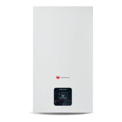
Identify the warning, do not guess the part.
If you Saunier Duval IsoMax Condens / MiConnect show a code, copy the complete message and check the model. Here you will find the warnings from its manual and what information to provide for a review. A code guides: it does not confirm by itself which spare part is needed.
Models and version of the manual
T35-CS/1 N-ES. The manual cover includes both names, IsoMax MiConnect and IsoMax Condens, for T35-CS/1 N-ES. Please confirm the full designation of your unit.
Consulted edition: 0020294189_03 · 02/08/2022 · manufacturer's manualThe control options, accessories, and versions may limit which notifications appear in each installation.
Locate the code on your screen.
These accesses lead to their entry in the table. They are not a classification of the most common faults: the manual does not provide incidence statistics.
- F.022
There is no water in the product, it is insufficient, or the water pressure is too low.
- F.028
During the ignition phase, the flame signal was not detected.
- F.029
The ignition failed due to lack of flame during operation.
- F.075
The pressure jump at the start of the heating pump is too low.
What to do without opening the boiler
- Note what you see.
Complete code, message, and pressure displayed by the equipment. Indicate whether it occurs when opening hot water, requesting heating, or in both cases.
- Identify the device.
Take a photo of the screen and the identification accessible without disassembling anything. Brand, model, and version help avoid confusing tables from different ranges.
- Describe how it started.
Determine whether the fault is continuous or intermittent and if there was a supply interruption or a recent intervention. If it reappears after a reset allowed by the user manual, do not chain resets.
Do not open the casing or manipulate gas, wiring, combustion, or flue gas outlet. If you smell gas, avoid flames and switches, leave the area, and notify the distributor's emergency service from a safe location; in case of immediate danger, call 112.
Documented codes table
The meaning of the warning is provided, not the repair operations reserved for qualified personnel. When the manufacturer groups several codes, the grouping is maintained; it is not interpreted as a range of numbers.
| Code | What does · source indicate? |
|---|---|
| F.000 | The signal from the supply temperature sensor has been interrupted. PDF |
| F.001 | The signal from the return temperature sensor has been interrupted. PDF |
| F.002 | The signal from the domestic hot water temperature sensor has been interrupted. PDF |
| F.003 | The signal from the temperature sensor of the accumulator has been interrupted. PDF |
| F.010 | A short circuit has occurred in the supply temperature sensor. PDF |
| F.011 | A short circuit has occurred in the return temperature sensor. PDF |
| F.012 | The temperature sensor of the hot water connection is short-circuited. PDF |
| F.013 | A short circuit has occurred in the temperature sensor of the accumulator. PDF |
| F.020 | The safety temperature limiter (STB) interrupts the control of the gas valve. The gas valve has closed because the temperature of the supply or return temperature sensor has exceeded the maximum limit. PDF |
| F.022 | There is no water in the product, it is insufficient, or the water pressure is too low. PDF |
| F.023 | The temperature difference between the supply and return is excessive. PDF |
| F.024 | The temperature increase is too rapid. PDF |
| F.025 | The temperature of the combustion gases is too high. PDF |
| F.027 | A flame signal was detected and the burner is off. PDF |
| F.028 | During the ignition phase, the flame signal was not detected. PDF |
| F.029 | The ignition failed due to lack of flame during operation. PDF |
| F.032 | The fan speed is out of tolerance. PDF |
| F.035 | The air intake/exhaust duct is blocked. PDF |
| F.040 | The air excess factor is too low. PDF |
| F.042 | The coding resistor (in the wiring harness) or the gas group resistor (on the PCB if it exists) is not valid. PDF |
| F.044 | The ionization signal of the regulation electrode is too low. The drift adaptation has failed. PDF |
| F.047 | The signal from the domestic hot water temperature sensor at the outlet of the internal accumulator is not plausible. PDF |
| F.049 | The eBUS is short-circuited or two active eBUS sources have reversed polarity. PDF |
| F.057 | The combustion regulation has failed and so has the corresponding emergency mode. PDF |
| F.061 | ASIC or µController does not operate within the defined time limits. PDF |
| F.062 | The flame disconnection is detected with a delay. PDF |
| F.063 | EEPROM warns of an error during the read and write test. PDF |
| F.064 | The sensor signal could not be converted correctly. PDF |
| F.065 | The operating temperature range of an electronic component has been exceeded. PDF |
| F.067 | The flame controller is faulty. PDF |
| F.068 | The flame controller reports an unstable signal. PDF |
| F.070 | The device identification (DSN) is incorrect, missing, or does not match the coding resistance. PDF |
| F.071 | The supply temperature sensor records implausible values. PDF |
| F.072 | The temperature difference between the supply and return temperature sensors is not valid. PDF |
| F.073 | The water pressure sensor is short-circuited. PDF |
| F.074 | The signal from the water pressure sensor is interrupted. PDF |
| F.075 | The pressure jump at the start of the heating pump is too low. PDF |
| F.077 | A condensate pump or a flue gas non-return valve block the operation of the burner. PDF |
| F.078 | The control module is not supported by the device. PDF |
| F.080 | The cold water inlet temperature sensor in the internal storage tank is faulty. PDF |
| F.081 | The boost has failed. PDF |
| F.083 | When starting the burner, no increase in temperature is recorded, or an increase is recorded too slowly on the supply or return temperature sensor. PDF |
| F.084 | The temperature difference between the supply and return temperature sensor results in implausible values. PDF |
| F.085 | The NTC sensors are incorrectly mounted. PDF |
| F.087 | The ignition transformer is not connected to the PCB. PDF |
| F.088 | The electrical connection with the gas valve has been interrupted. PDF |
| F.089 | The integrated heating pump is not suitable for the appliance model. PDF |
| F.092 | The gas type change has not been completed correctly. PDF |
| F.095 | The stepper motor of the gas valve has reached the minimum allowed number of steps. PDF |
| F.096 | The stepper motor of the gas valve has reached the maximum allowed number of steps. PDF |
| F.105 | If the gas valve or the PCB is replaced along with the device interface, the gas valve deviation must be adjusted to match the current gas valve. PDF |
| F.194 | The power supply of the PCB is faulty. PDF |
| F.195 | The device has detected a significant undervoltage in the power supply. PDF |
| F.196 | The device has detected a significant overvoltage in the power supply. PDF |
| F.317 | The flow sensor signal in the domestic hot water circuit is not plausible. PDF |
| F.318 | The 3-way motorised valve is not moving. PDF |
| F.320 | The heating pump is blocked. The unlocking function has not been performed correctly. PDF |
| F.321 | The pump electronics are faulty. PDF |
| F.322 | The heating pump is overheating. The emergency operation has not been able to reduce the temperature. PDF |
| F.323 | The heating pump is running dry. PDF |
| F.324 | The electrical connection of the pumps has been interrupted. PDF |
| F.325 | The heating pump has a fault. PDF |
| F.326 | The hydraulic test of the sensor and the actuator has determined that at least two hydraulic components are not functioning. PDF |
| F.327 | Due to a domestic hot water circuit not connected, the minimum volumetric flow rate of the heating is limited. PDF |
| F.344 | The regulation electrode cannot continue to be used. PDF |
| F.346 | A hard ignition has been detected. The ignition has failed. PDF |
| F.363 | The EEPROM on the display warns of an error during the read and write test. PDF |
| F.707 | It is not possible to establish any communication between the display and the PCB. PDF |
| F.905 | Communication interface disconnected PDF |
Is there a problem, but no fault code appears?
The absence of a warning does not rule out a fault. For a boiler that does not heat, does not deliver hot water, loses pressure, or operates intermittently, describe the symptom and the moment it occurs. Do not assume that the PCB, the pump, or a sensor is faulty without checking the equipment and the installation.
Request a review of the boiler. · Consult maintenance
Before requesting a repair
Does the code identify the spare part I need to buy?
No. A single warning can have multiple causes. The spare part reference requires identifying the appliance and confirming the fault; the code or a generic photograph is not sufficient.
Can it be reset again if the fault returns?
It is not advisable to chain resets. Follow only what is outlined for the user in your version's manual. A persistent or recurring lockout requires inspection.
When does it make sense to compare a new boiler?
When you have a diagnosis and a budget, compare repair, availability of the spare part, and replacement according to your installation. An isolated fault code does not justify changing the equipment.
Models of this guide in the catalog
See new boilers · Consult installation or replacement
The technical sheet of each product provides information on its price and availability. Installation is quoted separately depending on the case.
Documentation and other guides
Official manual of Saunier Duval IsoMax Condens / MiConnect · 0020294189_03 · 02/08/2022. The page references in the table correspond to the PDF viewer, whose numbering may differ from the printed version.
Consult fault guides by brand and model. · Return to the blog