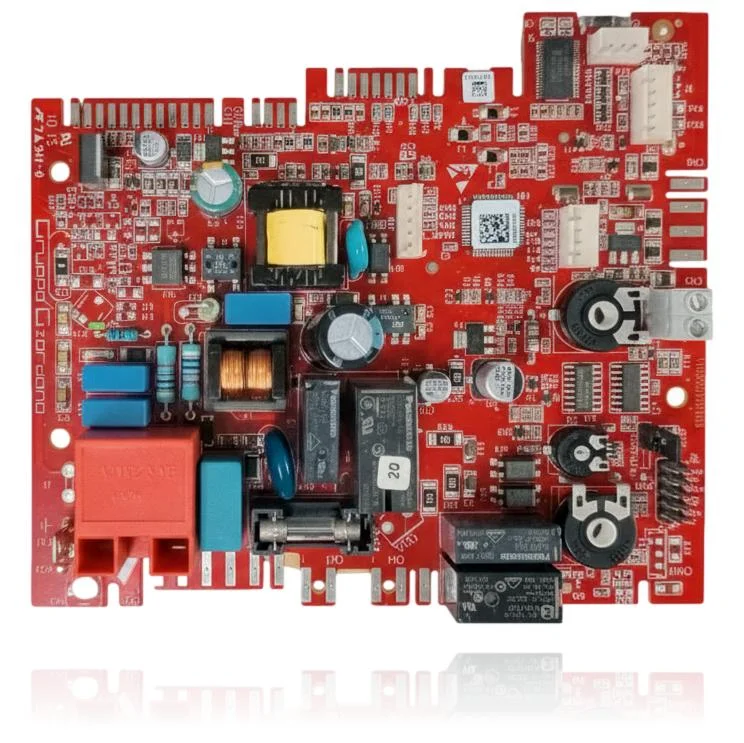
PCB Management Beretta Mynute Low NOx 24 CSI Ref. 20049611
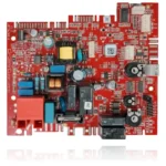
The Beretta Mynute Low NOx 24 CSI Control PCB, with reference 20049611, is responsible for controlling the ignition, burner modulation, pump, and safety features of the boiler. If it malfunctions, you will notice that the boiler does not start, locks out, or behaves erratically, potentially displaying alarms such as A01 or A11. This part is compatible with several models, including the Mynute Low NOx 24 CSI, Ciao S 24 CSI, and Mynute S 24 CSI, among others. It is recommended to replace it when the mentioned symptoms occur or if a replacement is needed following a fault diagnosis.
VAT included
Consult via WhatsAppBeretta boilers compatible with reference 20049611
PCB with reference 20049611. 15 verified compatibilities: Mynute Low NOx 24 CSI and Ciao S 24 CSI.
Proven compatibility
| Boiler model | Family | Verification |
|---|---|---|
| Beretta Mynute Low NOx 24 CSI | Mynute Low NOx | Contrasted |
| Beretta Ciao S 24 CSI | Ciao S | Contrasted |
| Beretta Ciao AT 25 CSI | Ciao AT | Contrasted |
| Beretta Ciao AT 29 CSI | Ciao AT | Contrasted |
| Beretta Mynute S 24 CSI | Mynute S | Contrasted |
| Beretta Mynute S 24 CAI | Mynute S | Contrasted |
| Beretta Mynute S 28 CSI | Mynute S | Contrasted |
| Beretta Mynute S 35 CSI | Mynute S | Contrasted |
| Beretta Mynute Boiler 24/45 BSI | Mynute Boiler | Contrasted |
| Beretta Mynute Boiler 28/60 BSI | Mynute Boiler | Contrasted |
| Beretta Mynute Boiler 28/60 BAI | Mynute Boiler | Contrasted |
| Beretta Mynute Sinthesi 25 CSI | Mynute Sinthesi | Contrasted |
| Beretta Mynute Sinthesi 29 CSI | Mynute Sinthesi | Contrasted |
| Beretta Meteo 24 CAI LX | Weather | Contrasted |
| Beretta Quadra II 24 CAI LX | Quadra II | Contrasted |
Can't see your model or have questions? The printed reference takes precedence. How to check it · Send us a photo via WhatsApp.
How to check if the ref. 20049611 is the part for your boiler
What determines it is not the boiler model, but the reference printed on the part you already have installed.
- Find the reference printed on the installed part and check whether it matches the catalogue reference 20049611. If it is not visible, do not identify the part from its shape alone.
- Check the full boiler model on its data plate and look for it in the model associations on this page.
- Compare the connections and physical body with the original part before installation.
- If anything is unclear, send us a photo of the marking via WhatsApp before placing your order.
Symptoms and faults that the PCB 20049611 resolves.
The PCB controls the ignition, modulation, and safety features of the boiler. These are the typical symptoms and what to do:
Common symptoms and faults
- 01
The boiler is completely dead: it doesn't even start the fan.
Cause: The control board does not distribute voltage to the other components, so they do not activate.
Check the internal fuse of the PCB and ensure that stable power is reaching the boiler before replacing it.
- 02
It turns on, makes a starting noise, but stops immediately showing a fault.
Cause: The PCB interrupts the cycle because a sensor informs it of an out-of-range condition and acts for safety reasons.
First, check the inlet NTC sensor and the pressure switch before considering the PCB as the culprit.
- 03
The indicators are flashing with a strange pattern that does not match any code in the manual.
Cause: This occurs when the microprocessor on the PCB has been damaged and does not manage the signals properly.
Cut the main power for one minute and then restore the power; if the flickering persists, point to the PCB.
- 04
The thermostat sets the temperature, but the boiler does not respond to the changes.
Cause: The PCB is the bridge between the thermostat and the burner; if it fails, it ignores the commands.
Force the manual ignition from the boiler itself to check if it responds without the thermostat in between.
Fault codes for Beretta that this part resolves.
| Code | Fault | Diagnosis and solution |
|---|---|---|
| A01 | ACF alarm lock module (ACF electronic fault alarm). | The MP05/ACF control board (PCB) manages ignition and flame detection; an internal fault in this electronics causes no spark/ionization reading and the boiler enters A01. Check HV output to electrode and 230 V to gas valve from the board; if gas/electrode are OK and the issue persists, test or replace the board. |
| A11 | Pilot flame. | The flame detection circuit on the PCB (ionisation) interprets flame current with the burner off due to drift/fault of the PCB and triggers A11. First check the siphon/condensate, ground, and electrode; if the false positive persists (even when isolating the electrode or with anomalous ionisation reading), the cause is the PCB. |
These symptoms can have more than one cause. If your boiler displays a fault code, send it to us via WhatsApp along with a photo of the labeling, and we'll tell you if this is the part.
Data sheet for the Beretta PCB 20049611
- Catalogue reference
- 20049611
- Brand
- Beretta
- Type of part
- PCBs (control boards)
- Units in stock
- 3 units
- Status
- Refurbished
- Warranty
- 1 year
- Shipping
- Delivery time shown at checkout
- Return
- 14 days
Manuals and technical documentation
Official documentation of the boiler, useful for locating the part and cross-referencing the fault codes.
- Beretta Mynute S 24 CSI Manual (PDF)Document © Beretta, provided as a technical reference.
Frequently asked questions about the PCB 20049611
Does this PCB with reference 20049611 fit a Beretta Ciao S 24 CSI?
Spare parts related to Beretta Mynute S