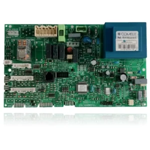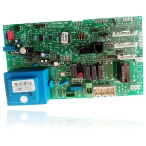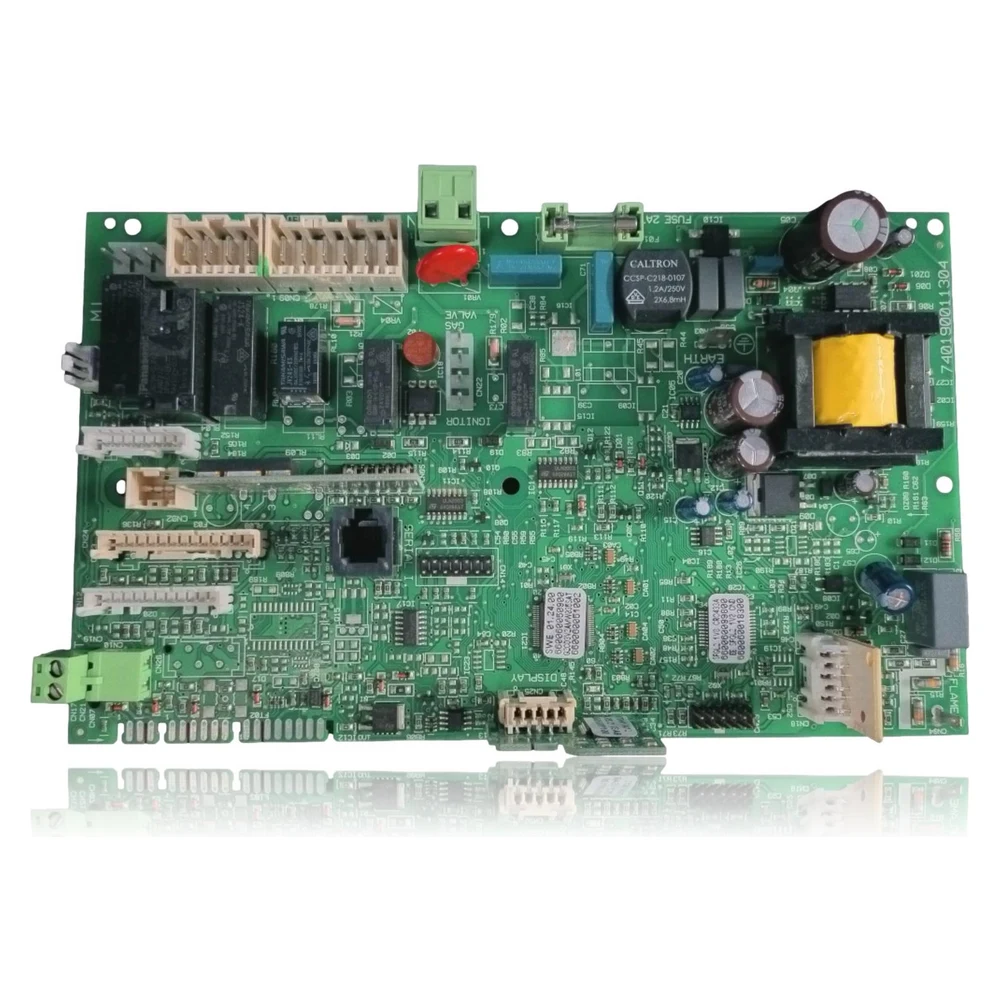
Main PCB Chaffoteaux Pigma 25 FF (GAL2-UNI ATM FULL) Ref. 740190011304
Main PCB GAL2-UNI ATM FULL for Chaffoteaux Pigma 25 FF boiler. Manages ignition, fan, pump, gas valve, and safety sensors. Identifiable by silkscreen 740190011304 and equivalence 65109313-05. Useful when errors 3xx or startup faults appear after checking power supply and peripherals.
VAT included
Consult via WhatsAppChaffoteaux boilers compatible with reference 740190011304
PCB with reference 740190011304. Six confirmed compatibilities from two independent sources: Pigma 25 FF and Pigma 30 FF.
Compatibility confirmed
| Boiler model | Family | Verification |
|---|---|---|
| Chaffoteaux Pigma 25 FF | Pigma | Confirmed · 2 sources |
| Chaffoteaux Pigma 30 FF | Pigma | Confirmed · 2 sources |
| Chaffoteaux Alixia 24 CF/FF | Alixia | Confirmed · 2 sources |
| Chaffoteaux Urbia 25/30 CF-FF | Urbia | Confirmed · 2 sources |
| Chaffoteaux Niagara C 25/30 FF | Niagara C | Confirmed · 2 sources |
| Chaffoteaux Talia 25/30 CF-FF | Talia | Confirmed · 2 sources |
Can't see your model or have questions? The printed reference takes precedence. How to check it · Send us a photo via WhatsApp.
How to check if the reference 740190011304 is the part for your boiler.
What determines it is not the boiler model, but the reference printed on the part you already have installed.
- Array
- Array
- Array
- Array
- Array
- Array
- Array
- Array
Symptoms and faults that the PCB 740190011304 resolves.
The PCB controls the ignition, modulation, and safety features of the boiler. These are the typical symptoms and what to do:
Common symptoms and faults
- 01
Repeated lockouts with fault codes 303/305 or 302
Cause: Internal faults of the PCB or display bus
Measure 230 V~ input, check fuse and 5 Vdc; test with known display/BUS cable.
- 02
No spark despite demand and ventilation being OK.
Cause: Ignition stage of the faulty PCB
Check high voltage at ignition, continuity of the electrode cable, and that the PCB sends the command.
- 03
Pump/fan does not start with demand.
Cause: Defective relays/outputs on the PCB
Apply technical demand (chimney sweep function), measure voltage at outputs; if there is no 230 V~ with correct peripherals, the PCB fails.
- 04
Incoherent pressure or temperature readings
Cause: Damaged analog input or sensor/wiring
Temporarily replace the sensor with a known one, check continuity; if it persists, PCB input.
- 05
Random restarts of the equipment
Cause: Unstable power supply or internal PCB source
Measure 230 V~, check the ground connection, measure 5/12 V DC on the PCB under load; if they drop, the PCB power supply is faulty.
Fault codes Chaffoteaux that this part resolves
| Code | Fault | Diagnosis and solution |
|---|---|---|
| 101 | Primary overtemperature | Check circulation (pump, filters, air), NTC of supply and return, and that the fan is exhausting. Relation to the PCB: if it does not power the pump/fan despite the correct command, or if the NTC reading is correct and persists, a possible PCB fault. |
| 108 | Lack of water / insufficient pressure | Fill installation up to ~1.0–1.5 bar and bleed. Check pressure switch/pressure sensor. Relation with the PCB: rarely; rule out sensor/wiring first. If measurement arrives but the display does not interpret it, suspect analog input of the PCB. |
| 109 | Installation pressure > 3 bar | Download due to safety valve/circuit and check expansion vessel. Regarding the PCB: check the signal from the transducer; if it is correct and the display shows >3 bar without being real, there may be a reading fault on the PCB. |
| 302 | Communication error between PCB and display | Check the bus/wiring, connectors, and 5 Vcc to the display. Disconnect/clean and test. If the issue persists with a tested display, there is likely a fault in the interface/bus of the PCB. |
| 303 | Main PCB fault | Cut/reset, check 230 V~, neutral and ground, PCB fuse and absence of shorts in peripherals. If it reappears with peripherals disconnected, PCB faulty. |
| 305 | Internal PCB error (variant) | Identical approach as in 303; check internal voltages (5/12 Vdc), fuse, and output consumption. If voltages are unstable, replace the PCB. |
| 501 | Flame absence | Check gas, ionization, electrodes and wiring, and spark. Relation to the PCB: if there is no spark/no voltage at the valve with conditions OK, possible fault in the ignition stage/output to valve on the PCB. |
| 608 | Unauthorized smoke pressure switch with fan on | Check the intake tubes, pressures, and fan. Regarding the PCB: if the fan is not receiving voltage, or if the pressure switch is reading incorrectly, check the PCB's inputs/outputs. |
These symptoms can have more than one cause. If your boiler displays a fault code, send it to us via WhatsApp along with a photo of the labeling, and we'll tell you if this is the part.
Data sheet for the Chaffoteaux PCB 740190011304
- OEM reference
- 740190011304
- Brand
- Chaffoteaux
- Type of part
- PCBs (control boards)
- Units in stock
- 11 units
- Status
- Refurbished
- Warranty
- 1 year
- Shipping
- 1-2 business days
- Return
- 14 days
Data read on the part and in the manufacturer's documentation
What we have not been able to verify does not appear here.
- Verified compatibility
- Pigma 25 FF (also Pigma 30 FF, Alixia 24 CF/FF, Urbia 25/30 CF/FF, Talia 25/30, Niagara C 25/30) with 65109313-05.
- OEM equivalents
- 65109313-05 (replaces 65109313-04 and 65105818-01).
- Identification on the PCB
- Silkscreen 740190011304; marking GAL2-UNI ATM FULL.
- Boiler power supply
- 230 V~ 50 Hz (according to the Pigma 25/30 FF manual, Spain).
- PCB dimensions (approx.)
- 216 × 130 mm.
- Typical related faults
- 302 (communication), 303/305 (PCB), 501 (absence of flame if there is no spark/gas output).
- Always disconnect the power supply and gas before intervening.
- Discharge static electricity; handle the PCB by the edges.
- The PCB fuse is single-use: if it blows, investigate the cause before replacing it.
- Do not bypass pressure switches or safety devices for testing.
- Use new gaskets in any hydraulic/gas disconnection.
- After the change, bleed the system and check combustion and tightness.
- Check and, if necessary, transfer/program the EEPROM and parameters of the model.
- Tighten terminals and ground connections with sufficient torque; vibrations loosen connections.
Frequently asked questions about the PCB 740190011304
Is it compatible with the Pigma Green 25/30 (condensing)?
Do I need to program the PCB when installing it?
I have fault codes 302 and 303 alternating, is it safe to say it's the PCB?
Why does 101 appear if the PCB is new?
Spare parts related to Chaffoteaux Pigma