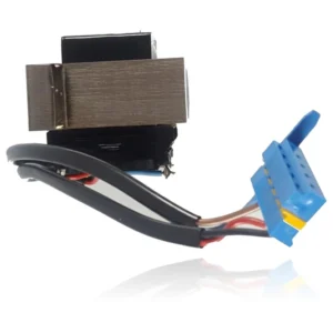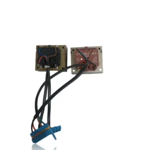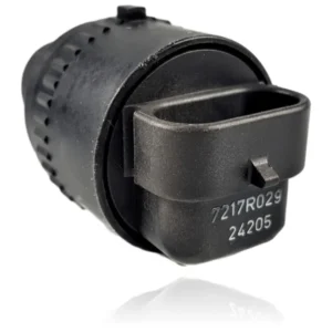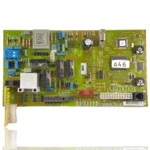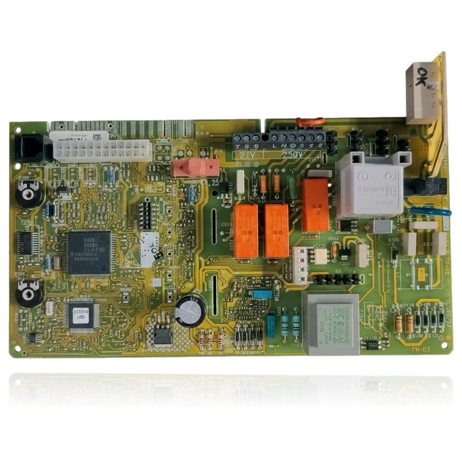
Vaillant PCB Control VMI 282 7 R3 Ref. 0020034604
When you open the hot water tap, the Vaillant Control PCB VMI 282 7 R3 Ref. 0020034604 is responsible for managing the ignition and modulation of the burner, as well as the pump and safety features of the boiler. If this part fails, you will notice that the boiler does not start, locks out, or operates erratically, potentially displaying fault codes such as F.63, F.64, or F.65. It is compatible with models from the VMW, VM, and VMI ranges, such as the VMI 282-7, among others. It is recommended to replace it when you experience these issues or if the boiler exhibits unusual behavior.
VAT included
Consult via WhatsAppVaillant boilers compatible with reference 0020034604
PCB with reference 0020034604. 14 verified compatibilities: VMW 240/2-3 and VMW 240/2-3 R1.
Proven compatibility
| Boiler model | Family | Verification |
|---|---|---|
| Vaillant VMW 240/2-3 | VMW (mixed turboTEC/turboMAX, wall-hung mixed) | Contrasted |
| Vaillant VMW 240/2-3 R1 | VMW (mixed turboTEC/turboMAX, wall-hung mixed) | Contrasted |
| Vaillant VMW 242/2-3 R1 | VMW (mixed turboTEC/turboMAX, wall-hung mixed) | Contrasted |
| Vaillant VMW 242/2-3 R2 | VMW (mixed turboTEC/turboMAX, wall-hung mixed) | Contrasted |
| Vaillant VMW 242-5 | VMW (mixed turboTEC/turboMAX, wall-hung mixed) | Contrasted |
| Vaillant VMW 280/2-5 | VMW (mixed turboTEC/turboMAX, wall-hung mixed) | Contrasted |
| Vaillant VMW 282/2-5 | VMW (mixed turboTEC/turboMAX, wall-hung mixed) | Contrasted |
| Vaillant VM 240/2-5 | VM (heating only) | Contrasted |
| Vaillant VM 242/2-5 | VM (heating only) | Contrasted |
| Vaillant VM 280/2-5 | VM (heating only) | Contrasted |
| Vaillant VM 282/2-5 | VM (heating only) | Contrasted |
| Vaillant VM 202/2-5 | VM (heating only) | Contrasted |
| Vaillant VMI 280-7 | VMI (compact interior) | Contrasted |
| Vaillant VMI 282-7 | VMI (compact interior) | Contrasted |
Can't see your model or have questions? The printed reference takes precedence. How to check it · Send us a photo via WhatsApp.
How to check if ref. 0020034604 is the part for your boiler
What determines it is not the boiler model, but the reference printed on the part you already have installed.
- Find the reference printed on the installed part and check whether it matches the catalogue reference 0020034604. If it is not visible, do not identify the part from its shape alone.
- Check the full boiler model on its data plate and look for it in the model associations on this page.
- Compare the connections and physical body with the original part before installation.
- If anything is unclear, send us a photo of the marking via WhatsApp before placing your order.
Symptoms and faults that the PCB 0020034604 resolves.
The PCB controls the ignition, modulation, and safety features of the boiler. These are the typical symptoms and what to do:
Common symptoms and faults
- 01
The boiler is not responding at all, neither the display nor the indicators, as if it has no power.
Cause: The network terminal of this PCB distributes power to the rest of the system; if that stage is damaged, no current reaches any component.
Check that 230-250V is reaching the network terminal of the PCB and that the internal fuse is not blown.
- 02
The home's control or thermostat has no effect on the boiler.
Cause: The heat demand enters through the 24V control terminal of this PCB; if the microprocessor does not process it, the boiler ignores the command.
Bridge the 24V control terminal on the PCB: if the boiler starts this way, check the thermostat and its cable.
- 03
The boiler locks out with a fault code as soon as you try to turn it on.
Cause: When the PCB detects an incoherent reading from its sensors during startup, it locks into safety mode before allowing gas to pass.
Write down the exact code: before changing the PCB, rule out that it points to water pressure, sensor, or flue gas evacuation.
- 04
The display is not visible or flickers, but you can hear the boiler trying to ignite.
Cause: The stage of the PCB that powers the display can fail independently of the rest of the control circuit.
Check the flat connector or the cable connecting the PCB to the display before replacing the entire board.
Fault codes from Vaillant that this part resolves.
| Code | Fault | Diagnosis and solution |
|---|---|---|
| F.63 | EEPROM error: fault in the configuration memory of the boiler's electronics. | The EEPROM physically resides on this main PCB; if the memory becomes corrupted or fails, the cause is the board itself. Verify: after a reset, the code persists and, with correct connections and sensors, the fault reproduces; confirm replacement of the board. |
| F.64 | Electronics error / NTC: fault in the electronics or short circuit in the flow/return NTC sensors. | When a short circuit in the NTC is ruled out (by checking sensors and wiring with a multimeter), the fault in the electronics processing those signals points to this main PCB. Verify: NTC and connections are correct but the fault code persists after reset = defective PCB. |
| F.65 | Temperature error in the electronics: the PCB is overheating. | The temperature sensor of the electronics itself detects excess heat on the PCB; if an external heat source or lack of ventilation is ruled out, the origin is a defect in the PCB. Verify: normal environment/ventilation but the code repeats = faulty PCB. |
| F.61 | Fault in the regulation/activation of the gas valve: the electronics cannot control the gas valve. | The PCB is the one that controls the gas valve; with wiring to ground, short circuit, and the valve itself ruled out using a multimeter, the remaining documented cause is the PCB. Verify: wiring and valve coils are correct but the code persists = defective PCB (the PCB is one of the causes, not the only one). |
| F.62 | Gas valve error due to delayed shutdown: delayed disconnection of the gas valve detected. | The PCB manages the closing/timing of the valve and the electrode signal; with the valve and detection electrode ruled out, the control electronics defect points to this PCB. Verify: valve and electrode are correct but the code repeats = PCB (concurrent cause with valve/electrode). |
These symptoms can have more than one cause. If your boiler displays a fault code, send it to us via WhatsApp along with a photo of the labeling, and we'll tell you if this is the part.
Data sheet for the Vaillant 0020034604 PCB.
- Catalogue reference
- 0020034604
- Brand
- Vaillant
- Type of part
- PCBs (control boards)
- Units in stock
- 1 unit
- Status
- Refurbished
- Warranty
- 1 year
- Shipping
- Delivery time shown at checkout
- Return
- 14 days
Data read on the part and in the manufacturer's documentation
What we have not been able to verify does not appear here.
- Control terminal voltage
- 24V
- Mains terminal voltage
- 250V
Manuals and technical documentation
Official documentation of the boiler, useful for locating the part and cross-referencing the fault codes.
- Vaillant VMI 282-7 Manual (PDF)Document © Vaillant, provided as a technical reference.
Frequently asked questions about the PCB 0020034604
What voltages does this PCB of the VMI 282-7 R3 carry?
Is this PCB Ref. 0020034604 suitable for a Vaillant VM 202-5?
Does the PCB Ref. 0020034604 work for a Vaillant VMW 240/2-3?
How many models are compatible with the Vaillant VMI 282 7 R3 control PCB?
What fault codes are documented for this PCB?
Where can I find the reference for this PCB?
Spare parts related to Vaillant VMW (combi turboTEC/turboMAX, wall-mounted combi)