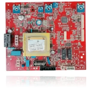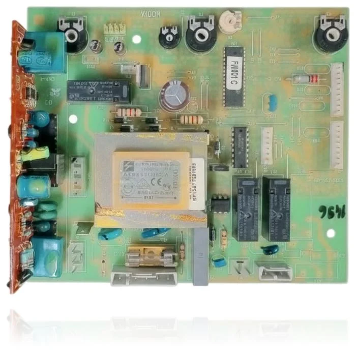
Beretta Ciao 24 CSI Control PCB Ref. 10023537
The control PCB for the Beretta Ciao 24 CSI N, with reference 10023537, manages the ignition, burner modulation, pump, and safety features of the boiler. If it fails, the boiler may not start, become locked, or operate erratically, displaying fault codes such as A01 or A11. This part is compatible with several models from the Beretta Ciao range, as well as some from the Arte and Riello Caldariello ranges, among others. It is recommended to replace it when these symptoms or operational faults occur.
VAT included
Consult via WhatsAppBeretta boilers compatible with reference 10023537
PCB with reference 10023537. Eight confirmed compatibilities: Ciao 24 CSI N and Ciao 24 CAI N.
Proven compatibility
| Boiler model | Family | Verification |
|---|---|---|
| Beretta Ciao 24 CSI N | Beretta Ciao | Contrasted |
| Beretta Ciao 24 CAI N | Beretta Ciao | Contrasted |
| Beretta Ciao 28 CSI N | Beretta Ciao | Contrasted |
| Beretta Ciao 28 CAI N | Beretta Ciao | Contrasted |
| Beretta Arte 24 CSI N | Beretta Arte | Contrasted |
| Beretta Arte 24 CAI N | Beretta Arte | Contrasted |
| Beretta Caldariello 24 KI N | Riello Caldariello | Contrasted |
| Beretta Caldariello 24 KIS N 3S | Riello Caldariello | Contrasted |
Can't see your model or have questions? The printed reference takes precedence. How to check it · Send us a photo via WhatsApp.
How to check if ref. 10023537 is the part for your boiler
What determines it is not the boiler model, but the reference printed on the part you already have installed.
- Find the reference printed on the installed part and check whether it matches the catalogue reference 10023537. If it is not visible, do not identify the part from its shape alone.
- Check the full boiler model on its data plate and look for it in the model associations on this page.
- Compare the connections and physical body with the original part before installation.
- If anything is unclear, send us a photo of the marking via WhatsApp before placing your order.
Symptoms and faults that the PCB 10023537 resolves.
The PCB controls the ignition, modulation, and safety features of the boiler. These are the typical symptoms and what to do:
Common symptoms and faults
- 01
The boiler does not ignite and does not show any indicator light.
Cause: If the electronic control fails, the boiler will not start even if it receives power.
Check the fuse on the PCB and make sure that the 230V power supply is arriving correctly before replacing it.
- 02
An error code appears that does not reflect a real problem in the installation.
Cause: The deterioration of the electronic control can lead to false alerts due to incorrect readings.
Compare the displayed code with the boiler manual and rule out the indicated component first before changing the PCB.
- 03
The room thermostat requests heat and the boiler does not respond at all.
Cause: The electronic control translates the thermostat signal into the boiler ignition command.
Check the wiring and terminals of the thermostat on the PCB before considering it faulty.
- 04
The boiler turns on and off quickly, as if it is resetting itself.
Cause: A fault in the relays of the electronic control can cause starts and stops without real demand.
Check if the behavior changes according to the ambient temperature of the boiler room: a thermal pattern may indicate a problem in the control.
Fault codes for Beretta that this part resolves.
| Code | Fault | Diagnosis and solution |
|---|---|---|
| A01 | Lockout due to ACF module (ACF/electronic ignition-flame fault). | The control board manages the ACF module; if its electronics fail, it does not trigger the ignition transformer or does not read the ionisation, and the boiler locks in A01. Check the spark output from the board and the ionisation current return; if the gas/electrodes are correct and there is no trigger/reading, the PCB is the cause. |
| A11 | Parasite flame (flame detection when there should be no combustion). | A fault in the flame detection circuit of the PCB (leakage/offset or grounding/polarity) causes the PCB to read ionisation with the burner off and generate A11. Check polarity and grounding, cable/electrode, and measure ionisation current with the gas closed; if false reading persists, the PCB is damaged. |
These symptoms can have more than one cause. If your boiler displays a fault code, send it to us via WhatsApp along with a photo of the labeling, and we'll tell you if this is the part.
Data sheet for the Beretta PCB 10023537
- Catalogue reference
- 10023537
- Brand
- Beretta
- Type of part
- PCBs (control boards)
- Units in stock
- 6 units
- Status
- Refurbished
- Warranty
- 1 year
- Shipping
- Delivery time shown at checkout
- Return
- 14 days
Data read on the part and in the manufacturer's documentation
What we have not been able to verify does not appear here.
- transformer code
- A04835036CA (Electron-Coil, Erbaicom Italy)
- transformer specification
- B59880-C120-A70
Frequently asked questions about the PCB 10023537
Is the Beretta Ciao 24 CSI N Control PCB Ref. 10023537 compatible with the Riello Caldariello 24 KI N?
What fault codes are common on this PCB?
How can I verify that this PCB is the correct one for my Beretta Arte 24 CAI N boiler?
How many models are compatible with the Beretta Ciao 24 CSI Control PCB Ref. 10023537?
What is the reference of the PCB that I need for my Beretta Ciao boiler?
Spare parts related to Beretta Ciao