






























































Short answer
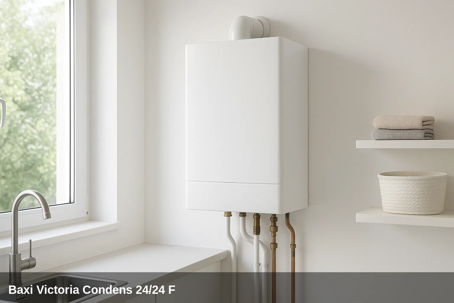
The Baxi Victoria Condens 24/24 F It is a wall-mounted gas condensing combi boiler, also marketed under the brand Baxi Roca (BDR Thermea), available in outputs 24/24 F and 28/28 FOffers 22 kW for heating and 24 kW for instantaneous domestic hot water, with energy classification A/C XL and integrated LCD screen. The fault codes are displayed on the screen in the format E.xx.xx (permanent lock) or H.xx.xx (non-blocking temporary anomaly).
Error code table for the Victoria Condens 24/24 F
Quick summary of all fault codes. Below you have the details of each one with its cause and solution.
| Code | Meaning |
|---|---|
| H.01.00 | Temporary communication failure between the gas valve and the PCB |
| H.01.05 | Excessive temperature difference between flow and return |
| H.01.08 | Excessively rapid increase in flow temperature in heating mode |
| H.01.14 | The maximum flow temperature value has been reached. |
| H.01.18 | Temporary lack of water circulation |
| H.01.21 | Excessively rapid increase in flow temperature in DHW mode |
| H.02.02 | Waiting for configuration parameter input (CN1, CN2) |
| H.02.03 | Incorrect configuration parameters entered |
| H.02.04 | Unreadable parameters of the PCB |
| H.02.06 | Low heating circuit pressure (temporary anomaly) |
| H.03.00 | Missing safety component identification |
| H.03.01 | Loss of communication with the comfort circuit (internal PCB error) |
| H.03.02 | Temporary flame loss |
| E.00.04 | Return temperature sensor disconnected |
| E.00.05 | Return temperature sensor in short circuit |
| E.01.04 | Flame loss detected 5 times in 24 hours |
| E.01.11 | Incorrect fan speed |
| E.01.12 | The temperature measured by the return sensor is higher than the flow sensor. |
| E.01.17 | Permanent lack of water circulation |
| E.01.20 | The maximum flue gas temperature has been reached. |
| E.02.00 | Boiler in reset phase |
| E.02.07 | Heating circuit pressure low (permanent) |
| E.02.16 | Communication error in the internal memory of the card (timeout exceeded) |
| E.02.17 | Permanent lack of communication between the gas valve and the PCB |
| E.02.19 | Modification of the state of the jumper J=1 (dip-switch) |
| E.02.20 | Modification of the state of the jumper J=2 (dip-switch) |
| E.02.21 | Modification of the state of the jumper J=3 (dip-switch) |
| E.02.47 | Fault in the external device connection (connector X14-A/X12-B) |
| E.02.48 | Fault in the external device configuration |
| E.04.00 | Gas valve anomaly |
| E.04.01 | Flow temperature sensor in short circuit |
| E.04.02 | Flow temperature sensor disconnected |
| E.04.03 | Maximum flow temperature exceeded (configuration) |
| E.04.04 | Flue temperature sensor in short circuit |
| E.04.05 | Flue temperature sensor disconnected |
| E.04.06 | Critical flue gas temperature exceeded |
| E.04.08 | Maximum safety temperature exceeded |
| E.04.10 | Burner ignition fault after 5 attempts |
| E.04.12 | Parasitic flame detection (ignition blocked) |
| E.04.13 | Fan rotor blocked |
| E.04.17 | Fault in the gas valve control circuit |
What can you check yourself?
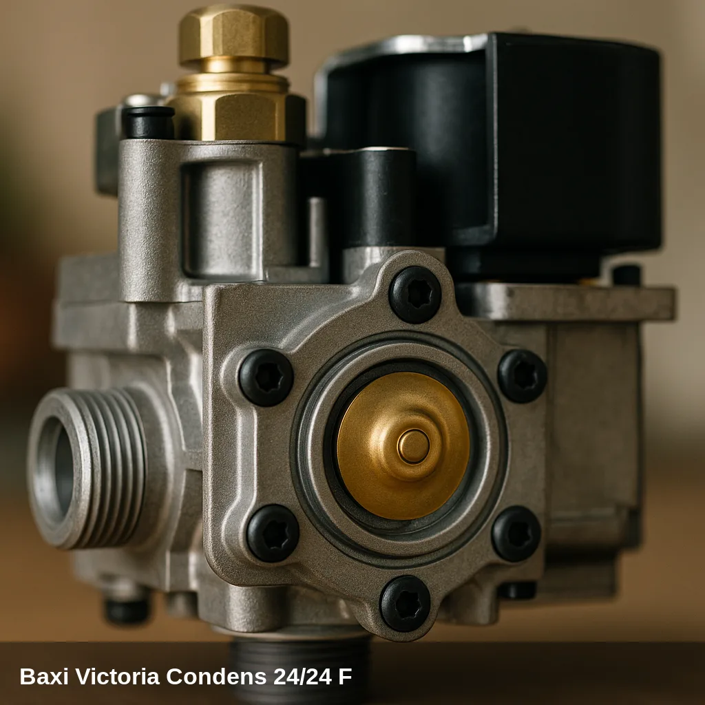
Some alerts can be resolved with simple and safe checks: replenishing the water pressure, bleeding the air from the radiators, checking that the gas valve is open, or resetting the boiler after a temporary lockout. If the code reappears after doing this, there is an underlying cause that should be reviewed by a qualified technician. Do not manipulate internal gas components nor electronics.
How to replenish the pressure step by step
- Locate the filling valve under the boiler.
- Open it slowly while observing the pressure gauge.
- Close the valve upon arrival at between 1 and 1.5 bar in cold.
- Bleed the radiators starting with the furthest one and check the pressure again.
- Reset the boiler; if the pressure warning disappears, the problem was resolved.
All fault codes and their solution
H.01.00 — Temporary communication failure between the gas valve and the PCB
Why does it appear: Internal card error or transient fault in the gas valve wiring
What to do: It is usually resolved automatically. If it persists, a qualified technician should check the connections of the gas valve and the condition of the PCB.
Affected component: Gas valve
H.01.05 — Excessive temperature difference between flow and return
Why does it appear: Insufficient water circulation in the heating circuit; possible presence of air or weak pump
What to do: Check the circuit pressure (it should be between 1 and 1.5 bar). Bleed the air from the system. Check the operation of the pump.
Affected component: Circulation pump
H.01.08 — Excessively rapid increase in flow temperature in heating mode
Why does it appear: Insufficient circulation or partially blocked pump
What to do: Bleed the system, check pressure, and ensure the pump is circulating correctly. Contact a qualified technician if the fault recurs.
Affected component: Circulation pump
H.01.14 — The maximum flow temperature value has been reached
Why does it appear: Insufficient water circulation or excessively high set temperature
What to do: Check the circuit pressure and bleed the air. Verify that the hydraulic circuits are not obstructed.
Affected component: Temperature sensor
H.01.18 — Lack of water circulation (temporary)
Why does it appear: Low pressure, presence of air in the circuit, or transient pump fault
What to do: Reset the pressure to the indicated level, bleed the system, and check the operation of the circulating pump.
Affected component: Circulation pump
H.01.21 — Excessively rapid increase in flow temperature in DHW mode
Why does it appear: Circulation problem or transient sensor fault in domestic hot water mode
What to do: Check pressure and bleed the circuit. If it persists, a qualified technician should check the flow temperature sensor.
Affected component: Temperature sensor
H.02.02 — Waiting for the introduction of configuration parameters (CN1, CN2)
Why does it appear: The boiler does not have the required installation parameters configured.
What to do: A qualified technician must enter the correct parameters using the CN1/CN2 connectors or the installation menu.
Related spare part: Baxi circuit board catalogue
H.02.03 — Configuration parameters entered incorrectly
Why does it appear: Incorrect configuration in the installation parameters (CN1/CN2)
What to do: A qualified technician must review and correct the installation parameters on the PCB.
Related spare part: Baxi circuit board catalogue
H.02.04 — PCB parameters unreadable
Why does it appear: Internal memory error in the PCB
What to do: A qualified technician must reconfigure or replace the PCB.
Related spare part: Baxi circuit board catalogue
H.02.06 — Low heating circuit pressure (temporary anomaly)
Why does it appear: Water loss in the installation or lack of pressure replenishment
What to do: Replenish the circuit pressure to 1.5 bar using the filling key. If the loss is recurrent, a qualified technician should check for possible leaks.
Browse catalogue: Catalogue: spare parts · Baxi
H.03.00 — Missing identification of safety component
Why does it appear: The PCB does not detect the corresponding safety component.
What to do: A qualified technician should check the connections of the safety components and the condition of the PCB.
Related spare part: Baxi circuit board catalogue
H.03.01 — Loss of communication in the comfort circuit (internal PCB error)
Why does it appear: Internal fault of the PCB or the connected thermostat/chronothermostat
What to do: A qualified technician should check the connections of the external control system and the condition of the PCB.
Related spare part: Baxi circuit board catalogue
H.03.02 — Temporary flame loss
Why does it appear: Irregular gas supply, dirty ionisation electrode, or transient flue gas evacuation issue
What to do: Verify that the gas supply is correct and that the flue is not obstructed. If it repeats, a qualified technician should inspect the electrode and the ionisation sensor.
Affected component: Ignition/Ionisation Electrode
E.00.04 — Return temperature sensor disconnected
Why does it appear: Loose connector or return temperature sensor in open circuit
What to do: A qualified technician should check the electrical connections of the return sensor and replace it if it is faulty. Press RESET once checked.
Affected component: Temperature sensor
E.00.05 — Return temperature sensor short-circuited
Why does it appear: Return temperature sensor deteriorated or with internal short circuit
What to do: A qualified technician must replace the return temperature sensor. Press RESET after the replacement.
Affected component: Temperature sensor
E.01.04 — Flame loss detected 5 times in 24 hours
Why does it appear: Insufficient gas pressure, deteriorated ionisation electrode, obstruction in the flue outlet, or condensate evacuation problems
What to do: Check that the gas supply is functioning correctly (other gas appliances are on). Press RESET. If it repeats, a qualified technician should inspect the ionisation electrode, the gas valve, and the flue system.
Affected component: Ignition/Ionisation Electrode
E.01.11 — Incorrect fan speed
Why does it appear: Fan motor fault or the PCB that controls it
What to do: A qualified technician should check the fan and its electrical connections. It usually requires replacement of the air-gas assembly.
Affected component: Fan / extractor
E.01.12 — The temperature measured by the return sensor is higher than the flow sensor.
Why does it appear: Temperature sensors reversed in their position, or one of them is faulty.
What to do: A qualified technician should verify the correct placement and identification of the flow and return sensors, and replace the defective one.
Affected component: Temperature sensor
E.01.17 — Lack of water circulation (permanent)
Why does it appear: Circulator pump faulty or blocked, very low pressure or defective sensor
What to do: Check the circuit pressure. A qualified technician should inspect the pump (possible rotor blockage), the electrical connections, and the circulation sensors.
Affected component: Circulation pump
E.01.20 — Maximum flue gas temperature reached
Why does it appear: Flue gas heat exchanger blocked by dirt or limescale, or faulty flue gas sensor
What to do: A qualified technician should clean the condensing heat exchanger and check the flue gas temperature sensor.
Affected component: Heat exchanger
E.02.00 — Boiler in reset phase
Why does it appear: The boiler is executing the reset cycle after a previous lockout.
What to do: Wait for the reset cycle to complete. If the lockout repeats, identify the underlying fault code and address its cause.
E.02.07 — Heating circuit pressure low (permanent)
Why does it appear: Water loss in the installation, discharged expansion vessel, or chronic pressure loss
What to do: Replenish the pressure to 1.5 bar using the filling valve. If the loss is recurrent, a qualified technician should locate and repair the leak, and check the expansion vessel.
Browse catalogue: Catalogue: spare parts · Baxi
E.02.16 — Communication error in the internal memory of the card (timeout exceeded)
Why does it appear: Internal fault of the PCB or electromagnetic interference
What to do: Press RESET. A qualified technician should check for possible sources of interference and, if the error persists, replace the PCB.
Related spare part: Baxi circuit board catalogue
E.02.17 — Permanent lack of communication between the gas valve and the PCB
Why does it appear: Fault in the gas valve wiring or defective PCB
What to do: A qualified technician should check the wiring and connectors of the gas valve. If the error persists, replace the PCB.
Affected component: Gas valve
E.02.19 — Modification of the state of the jumper J=1 (dip-switch)
Why does it appear: The position of the J1 configuration jumper has been changed without resetting the boiler.
What to do: Press RESET for 2 seconds for the boiler to accept the new configuration. Action reserved for qualified technician.
Related spare part: Baxi circuit board catalogue
E.02.20 — Modification of the state of the jumper J=2 (dip-switch)
Why does it appear: The position of the J2 configuration jumper has been changed without resetting the boiler.
What to do: Press RESET for 2 seconds for the boiler to accept the new configuration. Action reserved for qualified technician.
Related spare part: Baxi circuit board catalogue
E.02.21 — Modification of the state of the jumper J=3 (dip-switch)
Why does it appear: The position of the J3 configuration jumper has been changed without resetting the boiler.
What to do: Press RESET for 2 seconds for the boiler to accept the new configuration. Action reserved for qualified technician.
Related spare part: Baxi circuit board catalogue
E.02.47 — Fault in the connection of the external device (connector X14-A/X12-B)
Why does it appear: The external device connected (chronothermostat or other) is not establishing communication correctly.
What to do: A qualified technician should check the connections at terminals X14-A and X12-B and the correct pairing of the external device.
Affected component: Electrical installation
E.02.48 — External device configuration fault
Why does it appear: The external device connected has incorrect or incompatible configuration parameters.
What to do: A qualified technician should review the external device instructions and reconfigure the communication parameters.
Affected component: Electrical installation
E.04.00 — Anomaly in the gas valve
Why does it appear: Fault in the gas valve control circuit or defective PCB
What to do: A qualified technician should check the gas valve and its control circuit. It usually requires replacement of the PCB.
Affected component: Gas valve
E.04.01 — Flow temperature sensor short-circuited
Why does it appear: Damaged or internally short-circuited NTC flow sensor
What to do: A qualified technician should check the connections and replace the flow temperature sensor.
Affected component: Temperature sensor
E.04.02 — Flow temperature sensor disconnected
Why does it appear: Loose connector or broken cable of the flow sensor
What to do: A qualified technician should check the wiring and connectors of the flow sensor, replacing it if it is faulty.
Affected component: Temperature sensor
E.04.03 — Maximum flow temperature exceeded (configuration)
Why does it appear: Insufficient water circulation or excessively high set temperature; possible pump fault or closed valves
What to do: Verify that all hydraulic circuits are open. A qualified technician should check the pump and water circuits.
Affected component: Circulation pump
E.04.04 — Flue temperature sensor short-circuited
Why does it appear: Flue gas NTC sensor deteriorated with internal short circuit
What to do: A qualified technician must replace the flue temperature sensor.
Affected component: Temperature sensor
E.04.05 — Flue gas temperature sensor disconnected
Why does it appear: Loose connector or broken flue sensor cable
What to do: A qualified technician should check the wiring and connectors of the flue gas temperature sensor, replacing it if necessary.
Affected component: Temperature sensor
E.04.06 — Critical flue gas temperature exceeded
Why does it appear: Obstruction in the flue outlet or air intake, or very dirty heat exchanger
What to do: A qualified technician should check that the flue outlet and air intake are free of obstructions and clean the heat exchanger if necessary.
Affected component: Heat exchanger
E.04.08 — Maximum safety temperature exceeded
Why does it appear: Insufficient water circulation, safety thermostat triggered, pump blocked, or very low pressure
What to do: Check the circuit pressure. A qualified technician should inspect the pump, safety thermostat, and hydraulic circuits.
Affected component: Circulation pump
E.04.10 — Burner ignition fault after 5 attempts
Why does it appear: Lack of gas, dirty or deteriorated ignition electrode, defective ionization sensor, flue obstruction, or fan problem
What to do: Verify that the gas supply is correct (check other gas appliances). Press RESET. If the error persists, a qualified technician should inspect the electrode, the ionisation sensor, and the flue gas evacuation system.
Affected component: Ignition/Ionisation Electrode
E.04.12 — Detection of parasitic flame (ignition blocked)
Why does it appear: Fault in the grounding circuit, incorrect supply voltage, or ionization electrode with leakage to ground
What to do: A qualified technician must check the equipment's earth connection, the electrical supply voltage, and the insulation of the electrode cable.
Affected component: Ignition/Ionisation Electrode
E.04.13 — Fan rotor blocked
Why does it appear: Fan motor mechanically blocked or electrical fault in the fan
What to do: A qualified technician should check the fan, clean any obstructions, and replace the air-gas unit if the motor is damaged.
Affected component: Fan / extractor
E.04.17 — Fault in the gas valve control circuit
Why does it appear: Defective PCB or fault in the wiring of the gas valve control circuit
What to do: A qualified technician should diagnose the control circuit of the gas valve and replace the PCB if necessary.
Affected component: Gas valve
When to call a technician
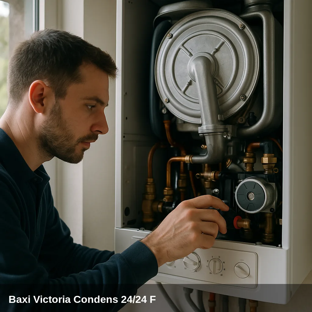
Fault codes related to sensors, electronics, gas valve, fan, or flue gas evacuation require a qualified technician with the appropriate equipment. If the same fault code reappears after a reset, or if the pressure drops repeatedly, a professional inspection is advisable. In Uniclima do you find spare parts for this boiler.
Frequently Asked Questions
For permanent lockout errors (E codes), the user can attempt a single reset by pressing the RESET button for 1 second. If the boiler locks out again with the same code, RESET should not be pressed repeatedly: the error indicates a fault that requires the intervention of a qualified technician to diagnose and resolve the root cause.
H codes (temporary anomaly) do not permanently lock the boiler and usually resolve themselves when the cause disappears (for example, when pressure is restored or temperature stabilizes). E codes (permanent anomaly) do lock the boiler until RESET is pressed and the cause is resolved. If an E code repeats after resetting, a review by a qualified technician is necessary.
Both codes indicate insufficient pressure in the heating circuit. The user can replenish the pressure by slowly opening the filling valve until the pressure gauge reads between 1 and 1.5 bar, then closing it. If the pressure drops recurrently, there is a leak in the installation that must be located and repaired by a qualified technician.
Fault code E.04.10 indicates that the boiler has attempted to ignite the burner 5 times unsuccessfully. The most common causes are: closed gas valve, gas supply cut-off by the distribution company, or an issue with the ignition electrode or ionisation sensor. First, check that other gas appliances in the home are functioning normally. If the supply is correct and the error persists after a RESET, the intervention of a qualified technician is required.