






























































Short answer
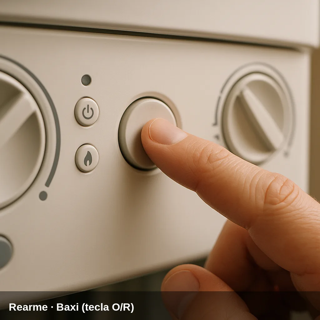
The Baxi Platinum Compact ECO (models -24/24 F, -26/26 F, and -30/30 F) is a wall-mounted gas condensing combi boiler from the Baxi Roca platform. It displays faults on the screen with the symbol E followed by a number. Some codes allow user reset by pressing the O/R button for 2 seconds; others require intervention from an authorised service technician. After 5 consecutive reset attempts, the boiler locks out and it is necessary to wait 15 minutes before making a new attempt.
Fault code table for the Platinum / Platinum Compact ECO
Quick summary of all fault codes. Below you have the details of each one with its cause and solution.
| Code | Meaning |
|---|---|
| E10 | External sensor fault |
| E12 | Lack of switching of the hydraulic differential pressure switch |
| E13 | Contacts stuck on the hydraulic differential pressure switch |
| E15 | Fault in the gas valve control board |
| E18 | Automatic filling of the hydraulic circuit in progress |
| E19 | Anomaly during the installation filling phase |
| E20 | Flow NTC sensor fault |
| E28 | Flue gas NTC sensor fault |
| E40 | Return NTC sensor fault |
| E50 | Faulty domestic hot water NTC sensor |
| E53 | Blocked flue duct |
| E55 | Uncalibrated PCB |
| E83 | Communication problem between the boiler PCB and the control unit (climate regulator) |
| E84 | Communication problem between the boiler PCB and the control unit (climate regulator) |
| E85 | Fault between the climate regulator and the receiver |
| E92 | Flue gas anomaly during the calibration phase (probable flue gas recirculation) |
| E109 | Presence of air in the boiler circuit (temporary anomaly) |
| E110 | Activation of the safety thermostat due to overheating |
| E117 | Pressure too high in the hydraulic circuit (above 2.7 bar) |
| E118 | Pressure too low in the hydraulic circuit |
| E125 | Safety activation due to lack of circulation in the circuit |
| E128 | Flame loss during operation |
| E129 | Flame loss during ignition |
| E130 | Activation of the flue gas NTC sensor due to overtemperature |
| E133 | Ignition failure after 5 attempts |
| E134 | Gas valve blocked |
| E135 | Internal error of the control board / Gas valve connection error |
| E154 | Test of the flow/return sensor control |
| E160 | Fan operation anomaly |
| E178 | Activation of the safety thermostat due to overheating in a low-temperature installation |
| E317 | Incorrect electrical supply frequency |
| E384 | Parasite flame (internal anomaly) |
| E385 | Electrical supply voltage too low |
| E321 | Faulty domestic hot water NTC sensor (variant of the DHW sensor) |
What can you check yourself?
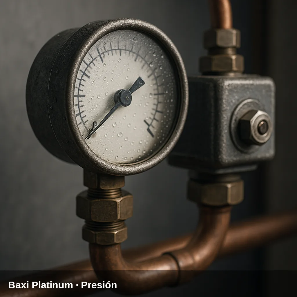
Some alerts can be resolved with simple and safe checks: replenishing the water pressure, bleeding the air from the radiators, checking that the gas valve is open, or resetting the boiler after a temporary lockout. If the code reappears after doing this, there is an underlying cause that should be reviewed by a qualified technician. Do not manipulate internal gas components nor electronics.
How to replenish the pressure step by step
- Locate the filling valve under the boiler.
- Open it slowly while observing the pressure gauge.
- Close the valve upon arrival at between 1 and 1.5 bar in cold.
- Bleed the radiators starting with the furthest one and check the pressure again.
- Reset the boiler; if the pressure warning disappears, the problem was resolved.
All fault codes and their solution
E10 — External sensor fault
Why does it appear: The outdoor temperature sensor has stopped sending a signal or is sending a value out of range. This may be due to a broken sensor, faulty wiring, or a disconnection.
What to do: Check the wiring and connectors of the external sensor. If the sensor is damaged, replace it. Requires an authorised technician.
Affected component: Temperature sensor
E12 — Lack of switching of the hydraulic differential pressure switch
Why does it appear: The differential pressure switch does not activate its contacts when it should, indicating a lack of water circulation or insufficient differential pressure in the primary circuit.
What to do: Check the operation of the pump and the flow rate of the circuit. If the pressure switch is faulty, replace it. Requires an authorised technician.
Browse catalogue: Catalogue: spare parts · Baxi
E13 — Stuck contacts in the hydraulic differential pressure switch
Why does it appear: The differential pressure switch has the contacts welded in the closed position, which prevents proper flow supervision.
What to do: Replace the differential pressure switch. Requires an authorised technician.
Browse catalogue: Catalogue: spare parts · Baxi
E15 — Error in the gas valve control board
Why does it appear: The PCB cannot correctly control the gas valve. It could be a fault in the wiring between the PCB and the valve, or an internal problem with the valve.
What to do: Check the wiring and connection of the gas valve connector. If the fault persists, inspect the valve and the PCB. Requires authorised technician.
Browse catalogue: Catalogue: gas valves · Baxi
E18 — Automatic filling of the hydraulic circuit in progress
Why does it appear: The boiler is running the automatic circuit filling cycle. It is a status indication, not necessarily a fault.
What to do: Wait for the filling cycle to complete. If the code persists for an extended period, it may indicate a leak in the installation.
Browse catalogue: Catalogue: spare parts · Baxi
E19 — Anomaly during the installation filling phase
Why does it appear: A problem has been detected during the automatic filling process: possible absence of water, insufficient pressure, or pressure switch fault.
What to do: Press the O/R key for 2 seconds to reset. Check that the water supply is open and the installation pressure is correct.
Browse catalogue: Catalogue: spare parts · Baxi
E20 — Faulty flow NTC sensor
Why does it appear: The flow temperature sensor to the heating circuit has failed: values out of range, open circuit or short circuit in the sensor or its wiring.
What to do: Measure the resistance of the NTC sensor and compare it with the values in the installer table. Replace if damaged. Requires authorised technician.
Affected component: Temperature sensor
E28 — Flue gas NTC sensor fault
Why does it appear: The flue gas temperature sensor has failed. It could be a broken sensor, faulty connection, or a short in the wiring.
What to do: Check the wiring and connector of the flue gas sensor. Replace the sensor if it is out of specification. Requires authorised technician.
Affected component: Temperature sensor
E40 — Return NTC sensor fault
Why does it appear: The return water temperature sensor of the heating circuit has failed: open circuit, short circuit, or sensor deterioration.
What to do: Measure the resistance of the return NTC sensor. Replace if the values do not correspond. Requires an authorized technician.
Affected component: Temperature sensor
E50 — Domestic hot water NTC sensor fault
Why does it appear: The domestic hot water temperature sensor has failed. It could be due to sensor breakage, ageing, or a fault in the wiring.
What to do: Check the DHW NTC sensor and its wiring. Replace if damaged. Requires an authorised technician.
Affected component: Temperature sensor
E53 — Flue duct blocked
Why does it appear: The flue pressure switch detects that the exhaust duct is totally or partially blocked, preventing the proper expulsion of combustion gases. It can also be activated by strong wind, accumulated condensate, or an animal nest in the duct.
What to do: Cut the power supply to the boiler for a few seconds and then turn it back on. If the error persists, check the flue and clean it. Requires an authorised technician.
Browse catalogue: Catalogue: heat exchangers · Baxi
E55 — PCB not calibrated
Why does it appear: The main PCB has not completed its calibration process or the internal parameters have remained uninitialized. This can occur after a replacement of the PCB or a fault in the internal memory.
What to do: Calibration must be carried out by an authorised technician using the specific commissioning procedure. Requires authorised technician.
Browse catalogue: Catalogue: circuit boards · Baxi
E83 — Communication problem between the boiler PCB and the control unit (climate regulator)
Why does it appear: Fault in the communication bus between the main board and the connected climate regulator. It could be a short circuit or break in the communication wiring, or a fault in the regulator.
What to do: Check the wiring of the climate regulator, ensure there are no short circuits or loose connections. If the regulator is disconnected, replace the jumper on terminal block M1. Requires an authorised technician.
Browse catalogue: Catalogue: circuit boards · Baxi
E84 — Communication problem between the boiler PCB and the control unit (climate regulator)
Why does it appear: Variant of communication fault E83. Probable short circuit or interruption in the bus wiring between the main board and the receiver or regulator.
What to do: Check the wiring of the climate regulator and the connectors. Verify that there are no electrical interferences. Requires an authorised technician.
Browse catalogue: Catalogue: circuit boards · Baxi
E85 — Error between the climate regulator and the receiver
Why does it appear: Communication failure between the programmable climate regulator (wireless or wired) and the receiver installed in the boiler. It could be due to loss of synchronization, low battery in the regulator, or faulty wiring.
What to do: Resynchronize the climate controller with the receiver according to the procedure in the controller's manual. If the problem persists, check the wiring. Requires an authorized technician.
Browse catalogue: Catalogue: circuit boards · Baxi
E92 — Flue gas anomaly during calibration phase (probable flue gas recirculation)
Why does it appear: During the boiler calibration process, the flue gas sensor detects anomalous values. The most common cause is a recirculation of combustion gases, which may be due to the installation of the flue in a location with adverse drafts.
What to do: Check the installation of the flue duct and ensure there is no recirculation of fumes. Requires an authorised technician.
Browse catalogue: Catalogue: heat exchangers · Baxi
E109 — Presence of air in the boiler circuit (temporary anomaly)
Why does it appear: Air bubbles have been detected in the primary hydraulic circuit. This usually occurs after filling the installation, following maintenance work, or when there are micro-leaks that introduce air.
What to do: Bleed the air from the circuit by opening the bleeders on the heat emitters and the boiler. If the fault occurs frequently, identify the source of the air ingress. Requires an authorised technician if it persists.
Browse catalogue: Catalogue: circulation pumps · Baxi
E110 — Activation of the safety thermostat due to overheating
Why does it appear: The water temperature has exceeded the safety thermostat threshold. The most common causes are: blocked circulation pump or insufficient flow, air in the primary circuit, dirty or scaled heat exchanger.
What to do: Press the O/R button for 2 seconds to reset once the boiler has cooled down. Check the pump, bleed the circuit, and inspect the condition of the heat exchanger. Requires an authorised technician if it repeats.
Browse catalogue: Catalogue: circulation pumps · Baxi
E117 — Pressure too high in the hydraulic circuit (above 2.7 bar)
Why does it appear: The pressure in the heating circuit has exceeded the safety limit of 2.7 bar. This may be due to a faulty expansion vessel, a filling valve stuck open, or excess water in the system.
What to do: Do not add more water. Check the condition and pre-charge of the expansion vessel. If the pressure does not drop to normal values, call technical service. Requires authorized technician.
Browse catalogue: Catalogue: spare parts · Baxi
E118 — Pressure too low in the hydraulic circuit
Why does it appear: The pressure in the heating circuit has dropped below the minimum threshold. Common causes: water loss due to a leak in the installation or in the safety valve, or partial draining of the circuit.
What to do: Fill the system using the filling tap (A) until reaching a pressure of 1 to 1.5 bar when cold. If the pressure frequently drops, look for the leak with an authorised technician.
Browse catalogue: Catalogue: spare parts · Baxi
E125 — Safety activation due to lack of circulation in the circuit
Why does it appear: The system detects through temperature sensors that there is insufficient water circulation in the primary circuit. Causes: blocked or faulty circulation pump, closed zone valves, clogged filter, or air in the circuit.
What to do: Press the O/R button for 2 seconds to reset. Check that the pump is running and that the zone valves are open. Bleed the circuit if there is air. Requires an authorised technician if it repeats.
Browse catalogue: Catalogue: circulation pumps · Baxi
E128 — Flame loss during operation
Why does it appear: The flame has gone out during normal operation. Causes: insufficient gas pressure, momentary interruption of gas supply, dirty or mispositioned ionisation electrode, or issues with the gas valve.
What to do: Press the O/R key for 2 seconds to reset. Check that the gas supply is open and that there is no pressure drop in the network. If it repeats, check the ionisation electrode and the gas valve. Requires authorised technician if it persists.
Affected component: Ignition/Ionisation Electrode
E129 — Flame loss on ignition
Why does it appear: The flame does not establish or is lost during the ignition phase. Causes: absence or low gas pressure, faulty ignition or ionisation electrode, gas valve not opening correctly.
What to do: Check the gas supply. Inspect the condition and position of the ignition and ionisation electrode. Requires authorised technician.
Affected component: Ignition/Ionisation Electrode
E130 — Activation of the flue gas NTC sensor due to overtemperature
Why does it appear: The flue gas temperature has exceeded the maximum allowable threshold. This may indicate dirt in the heat exchanger, a partially obstructed flue duct, or draught problems.
What to do: Press the O/R button for 2 seconds to reset. Check the condition of the heat exchanger and the flue duct. Requires an authorised technician.
Browse catalogue: Catalogue: heat exchangers · Baxi
E133 — Ignition failure after 5 attempts
Why does it appear: The boiler has attempted to ignite 5 consecutive times without successfully establishing a flame. Most common causes: absence or low gas pressure, closed gas valve, air in the gas circuit, dirty or deteriorated ignition electrode, gas valve not opening.
What to do: Check that the gas valve is open and that there is a supply. Press the O/R button for 2 seconds to reset. After 5 consecutive reset attempts, the boiler locks and you must wait 15 minutes. Requires an authorised technician if the issue persists.
Affected component: Ignition/Ionisation Electrode
E134 — Gas valve blocked
Why does it appear: The gas valve does not respond correctly to the open or close command from the PCB. It could be due to a mechanical fault in the valve, defective wiring, or a problem with the PCB.
What to do: Press the O/R button for 2 seconds to reset. If the error persists, check the gas valve and its wiring. Requires authorised technician.
Browse catalogue: Catalogue: gas valves · Baxi
E135 — Internal error of the control board / Gas valve connection error
Why does it appear: Internal fault in the main PCB, or a fault in the electrical connection between the PCB and the gas valve. This may include memory error, processor error, or control circuit error of the valve.
What to do: Requires diagnosis and possible replacement of the main PCB or the gas valve. Requires an authorised technician.
Browse catalogue: Catalogue: circuit boards · Baxi
E154 — Control test of the flow/return sensor
Why does it appear: The boiler is performing an internal verification test of the flow and return sensors, or it has detected a discrepancy between both readings that exceeds the allowed threshold.
What to do: Requires diagnosis by an authorised technician to check the condition of both NTC sensors and their wiring.
Affected component: Temperature sensor
E160 — Fan operation anomaly
Why does it appear: The fan does not reach the programmed revolutions or does not respond to the control signal. This may be due to mechanical obstruction of the impeller, motor wear, wiring failure, or a fault in the fan control module.
What to do: Check that the fan has no physical obstructions and that the wiring is properly connected. If the motor is damaged, replace the fan. Requires an authorised technician.
Affected component: Fan / extractor
E178 — Activation of the safety thermostat due to overtemperature in a low-temperature installation
Why does it appear: The boiler detects overheating in the circuit configured for low temperature (underfloor heating or a similar system). The pump may be blocked or the flow may be insufficient.
What to do: Requires inspection of the low-temperature circuit, the pump, and the mixing valves. Requires an authorised technician.
Browse catalogue: Catalogue: circulation pumps · Baxi
E317 — Incorrect electrical supply frequency
Why does it appear: The frequency of the electrical grid detected by the boiler does not correspond to the expected value (50 Hz in Spain). This may indicate severe instability of the electrical grid or a problem with the appliance's power supply.
What to do: Check the electrical installation of the house. If the electrical network is correct, inspect the power supply circuit of the boiler. Requires an authorised technician.
Affected component: Electrical installation
E384 — Parasitic flame (internal anomaly)
Why does it appear: The PCB detects a flame ionization signal when the burner should be off. It could be a fault with the ionization electrode, electrical leakage in the electrode wiring, or an internal fault in the PCB.
What to do: Press the O/R key for 2 seconds to reset. Check the ionisation electrode and its wiring. If it repeats, the control board may need replacement. Requires authorised technician.
Affected component: Ignition/Ionisation Electrode
E385 — Electrical supply voltage too low
Why does it appear: The mains voltage supplied to the boiler has dropped below the minimum operating threshold. This could be due to a voltage drop in the electrical network, tripped protections, or faulty power supply wiring.
What to do: The boiler automatically resets when the voltage exceeds 175 V. Check the electrical installation. If the anomaly persists, contact the authorised technical service.
Affected component: Electrical installation
E321 — Domestic hot water NTC sensor fault (DHW sensor variant)
Why does it appear: The DHW temperature sensor shows a value out of range, or there is an open circuit or short circuit in the sensor or its wiring. Fault code present in the climate regulator associated with the boiler.
What to do: Check the DHW NTC sensor and its connection. Replace if damaged. Requires authorised technician.
Affected component: Temperature sensor
When to call a technician
Fault codes related to sensors, electronics, gas valve, fan, or flue gas evacuation require a qualified technician with the appropriate equipment. If the same fault code reappears after a reset, or if the pressure drops repeatedly, a professional inspection is advisable. In Uniclima do you find spare parts for this boiler.
Frequently Asked Questions
Fault code E118 indicates low pressure in the hydraulic circuit. To resolve this, locate the filling tap (A) at the bottom of the boiler and open it slowly until the pressure gauge (B) reads between 1 and 1.5 bar with the system cold. Close the tap once that pressure is reached. If the pressure drops frequently, there may be a leak in the system and you should call an authorised technician.
The Baxi Platinum Compact ECO allows for 5 consecutive reset attempts by pressing the O/R button for 2 seconds. After these 5 attempts, the boiler locks out and it is necessary to wait 15 minutes before attempting a new reset. If the fault repeats after the reset, it indicates that the cause has not been resolved and you should call the authorised technical service.
The fault code E133 means that the boiler has attempted to ignite 5 times without success. The most common causes are: closed gas valve, lack of gas supply to the property, air in the gas pipe after a supply interruption, or a deteriorated ignition electrode. First, check that the gas valve (yellow, located below the boiler) is open and that other gas appliances in the property are working. If everything is correct, call the technical service.
When the symbol E appears next to a number on the screen, that number is the specific fault code. If the screen backlight flashes without displaying any numerical code, the boiler may be in a lockout state or standby mode. Refer to the fault section of the manual (section 4) to interpret the symbol displayed. If the symbol R also appears, the fault can be reset by the user; if it does not appear, it requires an authorised technician.