






























































Short answer
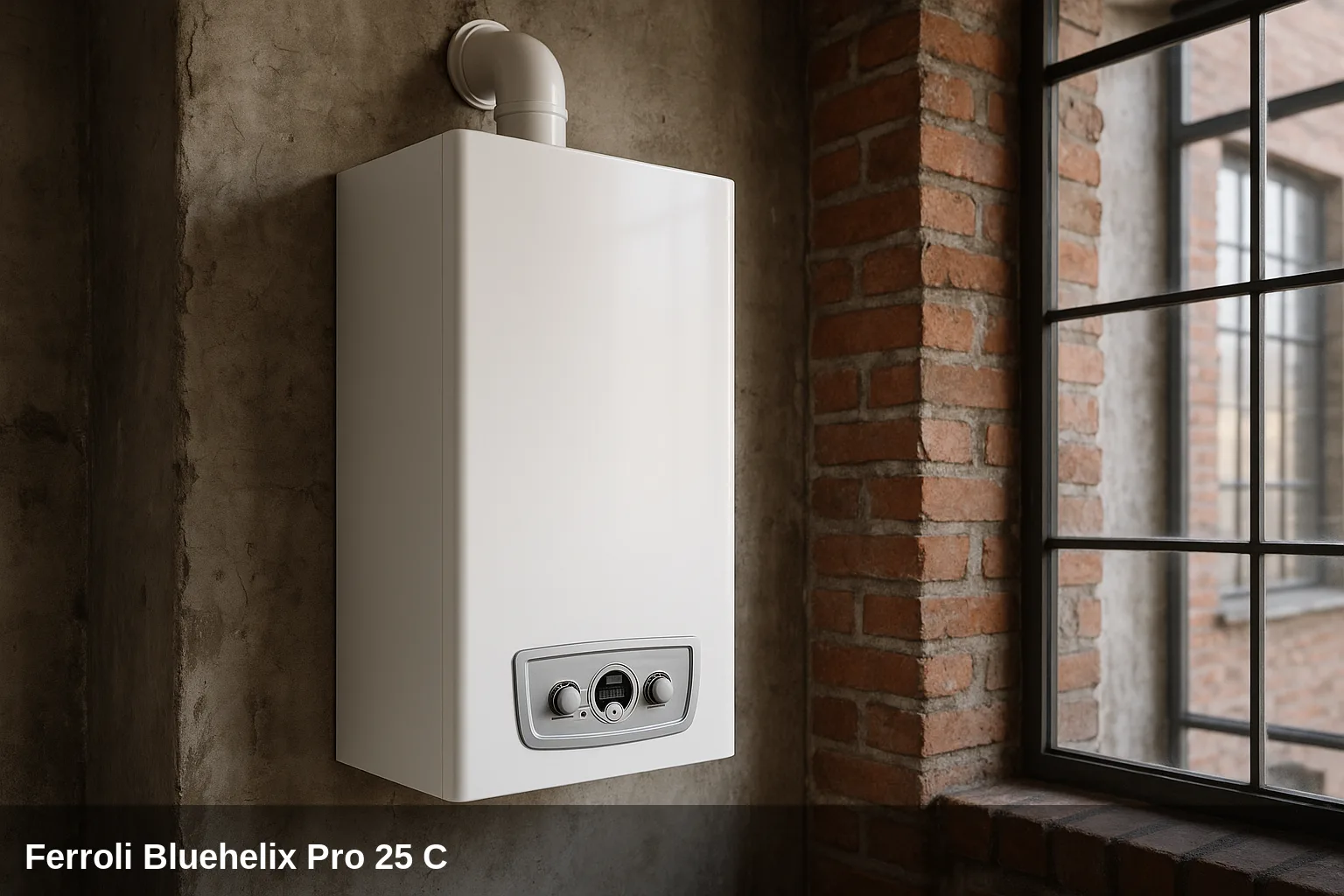
The Ferroli Bluehelix comprises two wall-mounted gas condensing boilers: the Bluehelix Pro 25 C (sealed chamber, micro-accumulation, up to 26.5 kW) and the Bluehelix Tech RRT 24 C (stainless steel heat exchanger, instant domestic hot water production, up to 24.5 kW in DHW). Both models share the error management architecture with type A codes (permanent lockout requiring manual reset) and type F codes (temporary anomaly that self-resets when the cause disappears). The A codes indicate active safety situations; the F codes are warnings of out-of-range operation. The manual reset is performed by pressing the reset button for less than one second. If the fault persists after the reset, the underlying cause must be diagnosed and resolved by a qualified technician.
Error code table for the Bluehelix Pro 25 C / Bluehelix Tech RRT 24 C
Quick summary of all fault codes. Below you have the details of each one with its cause and solution.
| Code | Meaning |
|---|---|
| A01 | Lockout due to burner ignition fault |
| A02 | Flame signal present with burner off (parasitic flame) |
| A03 | Activation of the overtemperature protection in the heating circuit |
| A04 | Activation of the flue safety device (permanent lockout) |
| A05 | Fan protection activation (permanent lockout) |
| A06 | Lockout due to absence of flame after ignition (six attempts in four minutes) |
| A23 | Parameter anomaly of the PCB |
| A24 | Parameter anomaly of the PCB |
| A26 | Water pressure switch anomaly or control board parameter |
| A41 | Activation of maximum temperature differential protection (maximum delta T) |
| A42 | Sensor control protection operation |
| A56 | Lockout due to incorrect or incomplete calibration |
| A61 | Internal anomaly of the control unit (AGC01 / ABM03) |
| A62 | No communication between the control unit and the gas valve |
| A64 | Maximum number of consecutive resets exceeded |
| F07 | Excessive flue gas temperature detected by the gas sensor |
| F10 | Primary circuit flow temperature sensor (NTC1) anomaly |
| F11 | Return temperature sensor anomaly |
| F12 | Domestic hot water (DHW) sensor anomaly |
| F13 | Flue sensor anomaly |
| F14 | Secondary flow temperature sensor (NTC2) anomaly |
| F15 | Fan fault |
| F20 | Parameter anomaly of the PCB |
| F21 | Parameter anomaly of the PCB |
| F34 | Supply voltage below 170 V |
| F35 | Abnormal electrical grid frequency |
| F37 | Incorrect water system pressure (low pressure) |
| F39 | External sensor anomaly (optional) |
| F40 | Parameter anomaly of the PCB |
| F41 | Activation of protection due to maximum delta T between flow and return |
| F43 | Operation of the heat exchanger protection |
| F47 | Parameter anomaly of the PCB |
| F52 | Heating sensor anomaly (secondary) |
| F56 | Calibration procedure not completed correctly |
| F61 | Internal anomaly of the control unit (AGC01 / ABM03) — temporary fault |
| F64 | Maximum number of consecutive resets exceeded — temporary fault |
| F66 | Firmware upload not completed or internal fault in the control unit |
| F51 | Safety thermostat (STB) anomaly — operation warning |
| F62 | Calibration required (new PCB or uncalibrated boiler) |
What can you check yourself?

Some alerts can be resolved with simple and safe checks: replenishing the water pressure, bleeding the air from the radiators, checking that the gas valve is open, or resetting the boiler after a temporary lockout. If the code reappears after doing this, there is an underlying cause that should be reviewed by a qualified technician. Do not manipulate internal gas components nor electronics.
How to replenish the pressure step by step
- Locate the filling valve under the boiler.
- Open it slowly while observing the pressure gauge.
- Close the valve upon arrival at between 1 and 1.5 bar in cold.
- Bleed the radiators starting with the furthest one and check the pressure again.
- Reset the boiler; if the pressure warning disappears, the problem was resolved.
All fault codes and their solution
A01 — Lockout due to burner ignition fault
Why does it appear: Lack of gas supply, dirty or damaged ignition or detection electrode, defective gas valve, insufficient gas pressure, obstructed air or flue ducts, blocked condensate trap
What to do: Check that the gas valve is open and there is supply. Verify the condition and position of the ignition and ionisation electrode. Inspect the gas valve and flue ducts. Bleed the condensate trap. If the issue persists, contact technical service.
Affected component: Ignition/Ionisation Electrode
A02 — Flame signal present with burner off (parasitic flame)
Why does it appear: Dirty ionisation electrode, short-circuited or incorrectly positioned. PCB anomaly
What to do: Inspect the wiring and the condition of the ionisation electrode. If the electrode is in good condition, check the PCB. Requires a qualified technician.
Affected component: Ignition/Ionisation Electrode
A03 — Activation of the overtemperature protection in the heating circuit
Why does it appear: Damaged or incorrectly positioned flow sensor, lack of water circulation (pump blocked or stopped), air in the system
What to do: Check the position and condition of the flow temperature sensor. Verify the operation of the circulating pump. Bleed the air from the system.
Affected component: Temperature sensor
A04 — Activation of the flue safety device (permanent lockout)
Why does it appear: Fault code F07 has been generated three times in the last 24 hours, indicating repeatedly excessive flue gas temperature.
What to do: Resolve the cause of fault F07 before attempting a reset: inspect the heat exchanger, the flue duct, and the flue sensor. Requires a qualified technician.
Browse catalogue: Catalogue: heat exchangers · Ferroli
A05 — Fan protection activation (permanent lockout)
Why does it appear: Fault code F15 has remained active for one consecutive hour, indicating a sustained fan anomaly.
What to do: Resolve the cause of fault F15: check the fan power supply, the tachometer signal, and the mechanical condition of the fan. Requires a qualified technician.
Browse catalogue: Catalogue: flue fans · Ferroli
A06 — Lockout due to absence of flame after ignition (six attempts in four minutes)
Why does it appear: Defective or poorly positioned ionisation electrode, unstable flame, gas valve with incorrect offset, obstructed air or flue ducts, blocked condensate trap, insufficient gas pressure
What to do: Check the position and condition of the ionisation electrode. Inspect the flue ducts and the condensate trap. Check the gas pressure. If the problem persists, a recalibration of the gas valve may be necessary. Requires a qualified technician.
Affected component: Ignition/Ionisation Electrode
A23 — Parameter anomaly of the PCB
Why does it appear: Incorrect configuration parameter of the PCB
What to do: Verify and correct the parameters of the PCB. Requires a qualified technician with diagnostic equipment.
Browse catalogue: Catalogue: circuit boards · Ferroli
A24 — Parameter anomaly of the PCB
Why does it appear: Incorrect configuration parameter of the PCB
What to do: Verify and correct the parameters of the PCB. Requires a qualified technician with diagnostic equipment.
Browse catalogue: Catalogue: circuit boards · Ferroli
A26 — Water pressure switch anomaly or control board parameter
Why does it appear: Incorrectly configured card parameter or anomaly in the water pressure switch
What to do: Verify the corresponding configuration parameter. Check the water pressure switch and its wiring. Requires a qualified technician.
Browse catalogue: Catalogue: spare parts · Ferroli
A41 — Activation of protection due to maximum temperature differential (maximum delta T)
Why does it appear: Flow or return sensor disconnected from the pipe, excessive temperature differential between flow and return, lack of circulation
What to do: Verify the correct placement and fastening of both sensors on the corresponding pipe. Check the operation of the pump. Bleed the air from the installation.
Affected component: Temperature sensor
A42 — Activation of protection by sensor control
Why does it appear: Heating or return sensor faulty or with poor connection
What to do: Check the position and condition of the heating and return sensors. Replace the faulty sensor. Requires a qualified technician.
Affected component: Temperature sensor
A56 — Lockout due to incorrect or incomplete calibration
Why does it appear: Calibration procedure not completed, electrode damaged or improperly positioned, insufficient circulation during calibration
What to do: Perform the calibration procedure at 100%. Check the condition and position of the electrode before recalibrating. Requires a qualified technician.
Affected component: Ignition/Ionisation Electrode
A61 — Internal anomaly of the control unit (AGC01 / ABM03)
Why does it appear: Internal fault of the control board, grounding issue, defective ionisation electrode
What to do: Check the boiler's grounding connection. Disconnect the power supply for ten seconds and reconnect. If the issue persists, replace the control unit. Requires a qualified technician.
Browse catalogue: Catalogue: circuit boards · Ferroli
A62 — No communication between the control unit and the gas valve
Why does it appear: Electrical connection interrupted between the PCB and the valve, defective gas valve
What to do: Check the wiring between the PCB and the gas valve. If the wiring is in good condition, replace the gas valve. Requires a qualified technician.
Related spare part: Ferroli gas valve catalogue
A64 — Maximum number of consecutive resets exceeded
Why does it appear: The boiler has been reset repeatedly without resolving the cause of the fault, indicating a persistent problem.
What to do: Disconnect the electrical supply for 60 seconds and reconnect. Do not reset without identifying and resolving the underlying cause. Requires a qualified technician.
Browse catalogue: Catalogue: circuit boards · Ferroli
F07 — Excessive flue gas temperature detected by the gas sensor
Why does it appear: Dirty or scaled heat exchanger, partially obstructed flue duct, incorrect chimney parameter, poorly positioned or faulty flue gas sensor
What to do: Inspect the heat exchanger and the flue ducts. Check the position of the flue gas sensor. If the error repeats three times in 24 hours, it goes to lockout A04.
Browse catalogue: Catalogue: heat exchangers · Ferroli
F10 — Anomaly in the primary circuit flow temperature sensor (NTC1)
Why does it appear: Damaged sensor, wiring short-circuited or interrupted
What to do: Check the continuity and condition of the sensor wiring. Measure the resistance of the NTC sensor. Replace the sensor if it is out of range. Requires a qualified technician.
Affected component: Temperature sensor
F11 — Return temperature sensor anomaly
Why does it appear: Return sensor damaged, wiring short-circuited or interrupted
What to do: Check the continuity of the wiring and measure the resistance of the sensor. Replace if it is out of range. Requires a qualified technician.
Affected component: Temperature sensor
F12 — Domestic hot water (DHW) sensor anomaly
Why does it appear: DHW sensor damaged, wiring short-circuited or interrupted
What to do: Check the continuity and condition of the wiring. Replace the sensor if it is faulty. Requires a qualified technician.
Affected component: Temperature sensor
F13 — Flue sensor anomaly
Why does it appear: Flue gas sensor faulty, wiring short-circuited or interrupted
What to do: Check the wiring and the sensor. Replace the sensor if it is out of range. Requires a qualified technician.
Affected component: Temperature sensor
F14 — Secondary flow temperature sensor (NTC2) anomaly
Why does it appear: Secondary flow sensor damaged, wiring short-circuited or interrupted
What to do: Check wiring continuity. Measure sensor resistance. Replace if out of range. Requires qualified technician.
Affected component: Temperature sensor
F15 — Fan anomaly
Why does it appear: Absence of electrical supply to the fan, interrupted tachometer signal, fan damaged or mechanically unbalanced
What to do: Check the wiring of the 3 and 5-pin connector of the fan. Verify the tachometer signal. If the fan is damaged, replace it. If the error persists for one hour, it goes to lockout A05.
Browse catalogue: Catalogue: flue fans · Ferroli
F20 — Parameter anomaly of the PCB
Why does it appear: Incorrect or corrupted configuration parameter of the PCB
What to do: Verify and reset the parameters of the PCB. Requires a qualified technician with diagnostic equipment.
Browse catalogue: Catalogue: circuit boards · Ferroli
F21 — Parameter anomaly of the PCB
Why does it appear: Incorrect or corrupted configuration parameter of the PCB
What to do: Verify and reset the parameters of the PCB. Requires a qualified technician with diagnostic equipment.
Browse catalogue: Catalogue: circuit boards · Ferroli
F34 — Supply voltage below 170 V
Why does it appear: Problem in the building's electrical network, voltage drop or poor electrical installation
What to do: Check the mains voltage at the boiler socket (it should be between 195 and 253 V). Inspect the building's electrical installation. If the voltage is correct, check the external 3 A fuse and the internal fuse on the PCB.
Affected component: Electrical installation
F35 — Abnormal mains frequency
Why does it appear: Irregularity in the supply electrical grid frequency
What to do: Check the frequency of the electrical grid. If the problem persists, contact the electricity distribution company.
Affected component: Electrical installation
F37 — Incorrect water pressure in the system (low pressure)
Why does it appear: Insufficient water pressure (below 0.5 bar), damaged, blocked, or disconnected water pressure switch
What to do: Refill the heating system until it reaches between 1 and 1.5 bar when cold. If the pressure is correct, check the condition and connections of the pressure switch. Check for possible leaks in the system.
Browse catalogue: Catalogue: spare parts · Ferroli
F39 — External sensor anomaly (optional)
Why does it appear: Damaged outdoor sensor, wiring short-circuited or disconnected after activating adaptive temperature mode
What to do: Check the wiring and condition of the external sensor. If the sensor is not installed, disable the adaptive temperature mode from the parameters. Requires a qualified technician.
Affected component: Temperature sensor
F40 — Parameter anomaly of the PCB
Why does it appear: Incorrect or corrupted configuration parameter of the PCB
What to do: Verify and reset the parameters of the PCB. Requires a qualified technician with diagnostic equipment.
Browse catalogue: Catalogue: circuit boards · Ferroli
F41 — Activation of protection due to maximum delta T between flow and return
Why does it appear: Insufficient circulation in the primary circuit, faulty heating or return sensor, boiler overheated
What to do: Open a domestic hot water tap, wait approximately two minutes until the burner turns off, and reset. Check the operation of the pump and bleed the air from the system.
Affected component: Temperature sensor
F43 — Activation of the heat exchanger protection
Why does it appear: Lack of water circulation in the system, air in the system, circulator pump stopped or blocked
What to do: Check the operation of the circulating pump. Bleed the air from the system. Verify that there are no closed valves in the heating circuit.
Browse catalogue: Catalogue: circulation pumps · Ferroli
F47 — Parameter anomaly of the PCB
Why does it appear: Incorrect or corrupted configuration parameter of the PCB
What to do: Verify and reset the parameters of the PCB. Requires a qualified technician with diagnostic equipment.
Browse catalogue: Catalogue: circuit boards · Ferroli
F52 — Heating sensor (secondary) anomaly
Why does it appear: Heating sensor faulty or with defective wiring
What to do: Check the sensor wiring. Measure the NTC resistance. Replace the sensor if it is out of range. Requires a qualified technician.
Affected component: Temperature sensor
F56 — Calibration procedure not completed correctly
Why does it appear: Calibration interrupted, electrode damaged or poorly positioned, insufficient circulation during the process
What to do: Repeat the calibration procedure at 100% from the beginning. Check the electrode condition before recalibrating. Requires a qualified technician.
Affected component: Ignition/Ionisation Electrode
F61 — Internal anomaly of the control unit (AGC01 / ABM03) — temporary fault
Why does it appear: Internal error of the control board PCB
What to do: Disconnect the electrical supply for ten seconds and reconnect. If the error persists, replace the control unit. Requires a qualified technician.
Browse catalogue: Catalogue: circuit boards · Ferroli
F64 — Maximum number of consecutive resets exceeded — temporary fault
Why does it appear: The boiler has been reset repeatedly without resolving the underlying cause.
What to do: Disconnect the electrical supply for 60 seconds and reconnect. Identify and resolve the cause of the original fault before resetting. Requires a qualified technician.
Browse catalogue: Catalogue: circuit boards · Ferroli
F66 — Firmware upload not completed or internal fault in the control unit
Why does it appear: Error during firmware update, internal fault of the PCB
What to do: Reload the firmware or replace the PCB. Requires a qualified technician.
Browse catalogue: Catalogue: circuit boards · Ferroli
F51 — Safety thermostat (STB) anomaly — operation warning
Why does it appear: Pump with reduced performance, insufficient pressure, incorrect configuration parameter
What to do: Check the operation of the circulating pump and the system pressure. Verify the configuration parameters. Requires a qualified technician.
Browse catalogue: Catalogue: circulation pumps · Ferroli
F62 — Calibration required (new PCB or uncalibrated boiler)
Why does it appear: Replacement of PCB or boiler that has not undergone the initial calibration procedure
What to do: Perform the full calibration procedure at 100%. Requires a qualified technician.
Browse catalogue: Catalogue: circuit boards · Ferroli
When to call a technician
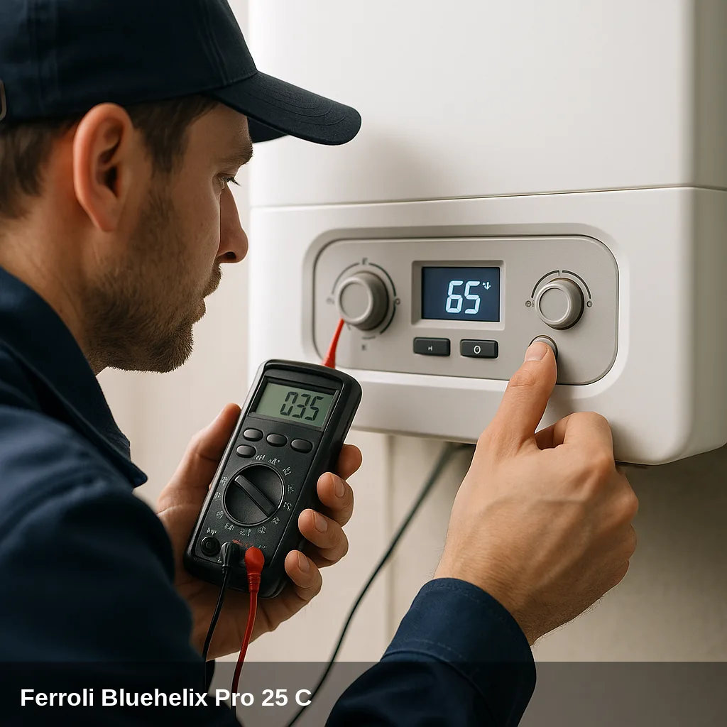
Fault codes related to sensors, electronics, gas valve, fan, or flue gas evacuation require a qualified technician with the appropriate equipment. If the same fault code reappears after a reset, or if the pressure drops repeatedly, a professional inspection is advisable. In Uniclima do you find spare parts for this boiler.
Frequently Asked Questions
Type A errors are permanent safety lockouts: the boiler shuts down and will not operate again until the reset button is pressed and the cause is resolved. Type F errors are temporary anomalies that the boiler manages autonomously and are cleared automatically when the condition that caused them disappears. If an F error occurs repeatedly, it may escalate to an A lockout.
Press the reset button (marked with a lightning bolt or the reset symbol) for less than a second. If the boiler does not start or the error reappears immediately, it means the cause has not been resolved. Do not reset the boiler more than two or three times in a row without identifying the problem, as doing so may trigger the A64 lockout for exceeding the maximum number of resets.
Yes, in most cases. Fault F37 indicates that the water pressure in the heating circuit is insufficient. The user can refill the system by opening the filling valve until the pressure gauge reads between 1 and 1.5 bar with the boiler cold. If the pressure drops frequently, there may be a leak in the system or a faulty expansion vessel, and it is necessary to call a technician.
Fault F07 indicates excessive flue gas temperature. If it occurs three times within a 24-hour period, the boiler escalates to permanent lockout A04 and cannot be reset until a qualified technician resolves the underlying cause, which is usually dirt in the heat exchanger, a blocked flue duct, or a faulty flue gas sensor.