

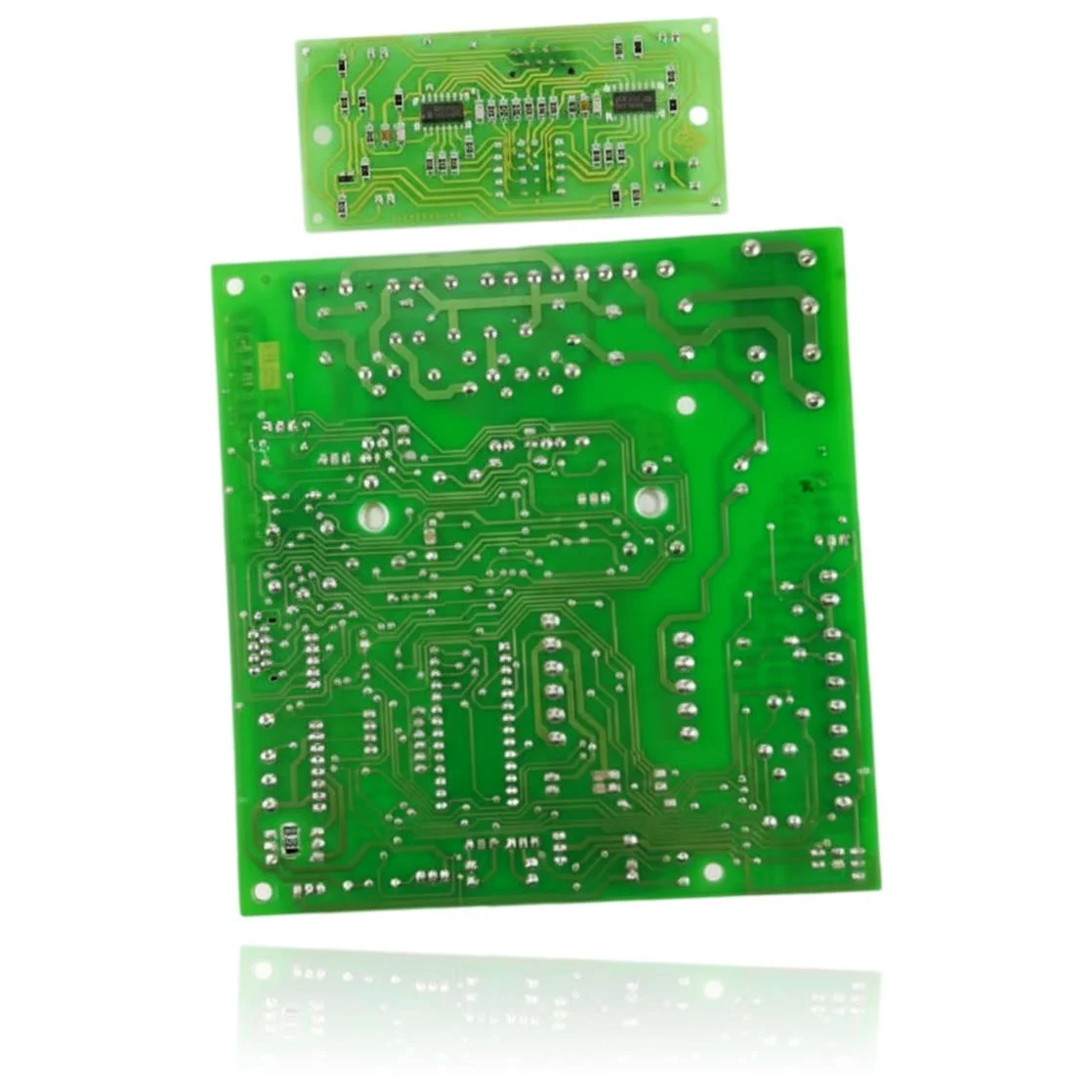
Immergas Eolo 24 Superior Plus PCB Ref. 018068
The Immergas Eolo 24 Superior Plus PCB is the component that controls the ignition, the modulation of the burner, the pump, and the safety features of the boiler. When it fails, the boiler may not start, become locked, or exhibit erratic behavior. Users may notice issues associated with fault codes such as E04, E15, E31, E37, or E01. This board is compatible with models from the Eolo Superior range, as well as with boilers from the Zeus Superior and Hercules ranges. A technician must confirm through diagnosis whether it is necessary to replace it when faults affecting the operation of the boiler are present.
- Type of part
- PCBs (control boards)
- Status
- Refurbished
- Catalogue reference
- 018068
- Warranty
- 1 year
Immergas boilers compatible with reference 018068
PCB with reference 018068. Seven confirmed compatibilities: Zeus 21 Superior and Zeus 24 Superior.
Proven compatibility
| Boiler model | Family | Verification |
|---|---|---|
| Immergas Zeus 21 Superior | Zeus Superior | Contrasted |
| Immergas Zeus 24 Superior | Zeus Superior | Contrasted |
| Immergas Zeus 27 Superior | Zeus Superior | Contrasted |
| Immergas Zeus 24 Extra | Zeus Superior | Contrasted |
| Immergas Eolo 24 Superior Plus | Eolo Superior | Contrasted |
| Immergas Hercules 24 | Hercules | Contrasted |
| Immergas Hercules 27 | Hercules | Contrasted |
Can't see your model or have questions? The printed reference takes precedence. How to check it · Send us a photo via WhatsApp.
How to check if ref. 018068 is the part for your boiler
The part reference, model, and equipment revision must be verified against the manufacturer's documentation.
- Find the reference printed on the installed part and check whether it matches the catalogue reference 018068. If it is not visible, do not identify the part from its shape alone.
- Check the full boiler model on its data plate and look for it in the model associations on this page.
- Compare the connections and physical body with the original part before installation.
- If anything is unclear, send us a photo of the marking via WhatsApp before placing your order.
Symptoms that require diagnosis on the PCB 018068
The PCB controls the ignition, modulation, and safety features of the boiler. These are the typical symptoms and what to do:
Common symptoms and faults
- 01
The boiler display does not turn on, is blank, or freezes with a fixed symbol.
Cause: The PCB includes the auxiliary display that shows the status and errors; if it fails, the screen stops updating or turns off even though the rest of the boiler tries to operate.
Cut the main power for 30 seconds and then restore it, as a temporary freeze of the display can be resolved this way without touching anything.
- 02
A fault code appears on the display that repeats constantly, even after resetting the boiler several times.
Cause: If the actual fault of the PCB is in the circuit that reads the sensors, it can generate the same fault code over and over again even if the component indicated is functioning properly.
Look up that specific code in your Immergas manual and first rule out the exact component it points to (pressure switch, NTC sensor, gas valve) before replacing the PCB.
- 03
The boiler repeatedly locks itself and needs to be reset several times a day.
Cause: An intermittent fault in the control electronics can cause safety lockouts without a real cause in gas, water, or venting.
Keep track of what time and under what situation it gets blocked (domestic hot water, heating, cold start) to distinguish a sensor pattern from a generic PCB fault.
- 04
None of the buttons on the boiler panel respond, not even to check the pressure or change the mode.
Cause: All the front buttons pass through this PCB before being translated into an action; if its input circuit fails, the boiler stops responding to the panel even though it continues heating.
Try operating the boiler from the thermostat or external control to determine if the problem is with this PCB or another component.
Immergas fault codes that require diagnosis
| Code | Fault | Technical checks |
|---|---|---|
| E04 | Lockout due to contact resistance / damaged PCB hardware | The modulation PCB detects an anomaly in the power supply to the gas valve; if the wiring and valve are correct, the hardware of the board is damaged. Check the connection to the valve and, if it persists after a reset, replace the PCB. |
| E15 | Wiring configuration error | The PCB recognises the type of boiler by jumpers/wiring (e.g., bridge 6–7 on X7); if the configuration and continuity (X7/X9) are correct and the error persists, the fault is with the PCB. Check bridges/continuity and replace the PCB if necessary. |
| E31 | Loss of remote control communication | BUS transceiver fault on the PCB prevents communication with CAR/CARV2 despite correct wiring. Check polarity and dedicated line (terminals P.C.B. 42–43/40–41) and, if the control board is fine, replace the PCB. |
| E37 | Low power supply voltage | If the mains (230 V ±10%) and external fuses/wiring are correct and the error persists, the internal power supply of the PCB is defective. Measure >190 VAC at the input; if correct and E37 remains, replace the PCB. |
| E01 | Lockout due to ignition failure | After checking the spark, voltages to the igniter/gas valve, and electrodes/gas are correct, the electronic module does not control the ignition. Follow the measurements on the indicated connectors and, if necessary, replace the PCB. |
| E20 | Lockout due to parasitic flame | With the detection electrode and wiring in good condition, the detection circuitry on the PCB interprets the flame as non-existent. Confirm electrode/ground; if the issue persists, replace the PCB. |
These symptoms can have more than one cause. If your boiler displays a fault code, send it to us via WhatsApp along with a photo of the labeling, and we'll tell you if this is the part.
Data sheet for the Immergas PCB 018068
- Catalogue reference
- 018068
- Uniclima internal SKU
- CEPMIZ1301
- Brand
- Immergas
- Type of part
- PCBs (control boards)
- Units in stock
- 1 unit
- Status
- Refurbished
- Warranty
- 1 year
- Shipping
- Delivery time shown at checkout
- Return
- 14 days
Part data and available documentation
Contrast the label codes, PCB, and revision with the installed part; they are not necessarily equivalent references.
- Code printed next to the Immergas logo
- 1301
Manuals and technical documentation
Official documentation of the boiler, useful for locating the part and cross-referencing the fault codes.
- Immergas Eolo 24 Superior Plus Manual (PDF)Document © Immergas, provided as a technical reference.
Frequently asked questions about the PCB 018068
Is this PCB suitable for the Immergas Hercules 24-27?
What text is on the integrated circuit label of this Zeus Superior PCB?